aha, the amplifier only serves as a basis for converting it into a hybrid amplifier ⁉️
http://triesteaudio.blog.fc2.com/blog-entry-298.html
http://triesteaudio.blog.fc2.com/blog-entry-294.html

http://triesteaudio.blog.fc2.com/blog-entry-298.html
http://triesteaudio.blog.fc2.com/blog-entry-294.html
Last edited:
I fired up the amp for the first time today, just to check the voltages. I got 300V DC and 6.8VAC for heating.
From what I read and expected, 6,8V it too high, but what about 300V on the DC supply?
I'm thinking about trying the bucking transformer if I can find one in my boxes that could work. Maybe that could keep the transformer a bit cooler too, since I see people having issues with that?
From what I read and expected, 6,8V it too high, but what about 300V on the DC supply?
I'm thinking about trying the bucking transformer if I can find one in my boxes that could work. Maybe that could keep the transformer a bit cooler too, since I see people having issues with that?
I notice two things with this Nobsound amplifier built as designed:
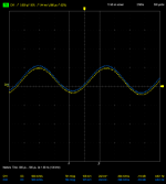
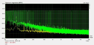
* The left channel (blue) seems louder than the right one (yellow), and comparing the output signal, this seems to be the case. This is annoying...
* Somehow, the negative phase is weaker than the positive phase, on both channels. Why?
I left those 27K / 30K resistors as they are, for now.
* The left channel (blue) seems louder than the right one (yellow), and comparing the output signal, this seems to be the case. This is annoying...
* Somehow, the negative phase is weaker than the positive phase, on both channels. Why?
I left those 27K / 30K resistors as they are, for now.
Attachments
@Rallyfinnen That sounds perfectly normal if unloaded. The voltages will drop significantly once you're actually heating tubes. Remember voltage drop is I * R, so if current is 0, voltage will be high.
Nobody I know used different value resistors in a cathodyne for hi-fi ... probably just a weird chinese idea to produce distortion "tube sound" expected by some noobs 🙂
Last edited:
@Depanatoru, actually, I tried replacing those 27kOhm resisters with 30kOhm ones. I got all sorts of weird feedback problems.
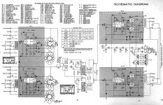
Please search more ... if you look , the supply for G2 of the pentode is the cathode of the triode , very unusual , maybe very clever local feedback , but has nothing to do with a simple cathodyne used in the chinese schematic and billions moreUnbalanced phase splitter resistors are common. Below is Dynaco SCA35- R32 & R34
Last edited:
That was loaded with tubes 🙁@Rallyfinnen That sounds perfectly normal if unloaded. The voltages will drop significantly once you're actually heating tubes. Remember voltage drop is I * R, so if current is 0, voltage will be high.
I made a 'bucking transformer extension cord' from an old wall wart, and that reduced the mains voltage with abt 15V, and the filament voltage went down to 6,38V..
I did some measurements on the amp today, will post some of that soon.

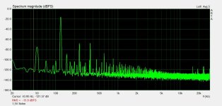
Wanted to do some measurements on this amp to have a 'baseline' of the performance, and also since I have not seen any posted here.
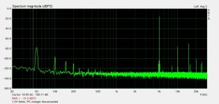
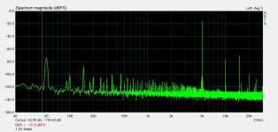
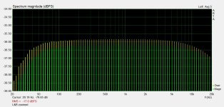
I ran some multitone measurements for IMD, a couple of pure sine signals to see harmonic spectrum of the distortion. Also had a look at the channel balance, channel separation and frequency response. I also tested a multitone with and without the bucking transformer to get an indication if voltage had any influence on the distortion, seemingly not.
At first I had significant hum in the measurements, and that turned out to be a ground loop in the measurement, so after I disconnected the PS to the laptop, it was a lot better. This is the reason you see variations in the 50Hz and related overtones between measurements.
My listening impressions:
+no hum heard from speakers, only slight hiss from tweeters up close. (I had a lot of hum before I grounded center tap on filament winding)
+soft and 'pleasant' sound, especially on acoustic instruments and voices
+nice 'soundstage' with and depth
-a bit 'tizzy' treble, not so clear and detailed, cymbals not as natural sounding
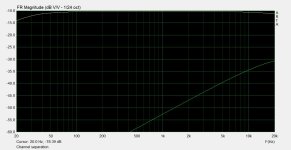
-lacks a bit in the lower end control and also less deep bass. FR drop off can be seen on FR graph too
-a bit low on power for low efficiency modern speakers
-less impressive sound with 'busy' music (I listen to a lot of heavy metal etc)
I ran some multitone measurements for IMD, a couple of pure sine signals to see harmonic spectrum of the distortion. Also had a look at the channel balance, channel separation and frequency response. I also tested a multitone with and without the bucking transformer to get an indication if voltage had any influence on the distortion, seemingly not.
At first I had significant hum in the measurements, and that turned out to be a ground loop in the measurement, so after I disconnected the PS to the laptop, it was a lot better. This is the reason you see variations in the 50Hz and related overtones between measurements.
My listening impressions:
+no hum heard from speakers, only slight hiss from tweeters up close. (I had a lot of hum before I grounded center tap on filament winding)
+soft and 'pleasant' sound, especially on acoustic instruments and voices
+nice 'soundstage' with and depth
-a bit 'tizzy' treble, not so clear and detailed, cymbals not as natural sounding
-lacks a bit in the lower end control and also less deep bass. FR drop off can be seen on FR graph too
-a bit low on power for low efficiency modern speakers
-less impressive sound with 'busy' music (I listen to a lot of heavy metal etc)
Attachments
-
 R 5kHz 1,5V 8ohm no PC charger.jpg76.5 KB · Views: 64
 -
 R 5kHz 1,5V 8ohm.jpg79.5 KB · Views: 65
 -
 R 5kHz 4V 8ohm.jpg79.9 KB · Views: 65
 -
 R 120Hz 1,5V 8ohm.jpg81.6 KB · Views: 74
 -
 R 120Hz 4V 8ohm.jpg84 KB · Views: 71
 -
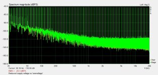 Reduced voltage vs overvoltage multitone.jpg112.7 KB · Views: 69
 -
 R 1kHz 4V 8ohm.jpg79.8 KB · Views: 73
 -
 R 1kHz 1,5V 8ohm.jpg79.5 KB · Views: 74
 -
 L multitone.jpg119.1 KB · Views: 67
 -
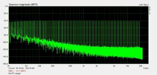 L & R multitone no PC charger.jpg103.5 KB · Views: 62
 -
 L & R multitone listening level.jpg113 KB · Views: 63
 -
 L & R multitone listening level zoom.jpg107.9 KB · Views: 67
 -
 L & R FR sweep.jpg70.7 KB · Views: 68
 -
 channel separation sweep.jpg65.2 KB · Views: 67
 -
 channel separation multitone.jpg103.1 KB · Views: 61
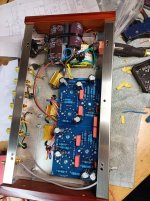
Some more pics of the build and clipping waveforms at 200, 1k and 5kHz. 5V/div feeding 8ohm load.
I had some beefier 680uF caps from a scrapped inverter, so I used one on the amp side of the PS CRC. Should have nice specs for ripple and also 105degC rated. Inverter was barely used, so cap should be fine.
The inside pic is during the build, so everything is not connected yet, and I had to swap the output leads after connecting the feedback, as described earlier in the thread.
Thinking about it afterwards, I should have scoped a square wave too, maybe there is something with the feedback stability/compensation making it sound 'tizzy'. Later..
EDIT:
Maybe small caps across the inputs to keep out HF would be a good idea too.
It seems transformer temps are ok using the bucking transformer to lover voltage. I saw some comments about that before.
Attachments


Last edited:
Oh wow, that's a lot.That was loaded with tubes 🙁
I made a 'bucking transformer extension cord' from an old wall wart, and that reduced the mains voltage with abt 15V, and the filament voltage went down to 6,38V..
I did some measurements on the amp today, will post some of that soon.
I measured mine, too, loaded, and got something pretty high (7V I think). I added a big 0.2W resistor to the heating circuit, and now I'm at 6.5V which is within spec I believe.
Apart from the clipping there seems to be a lot of cross-over distortion. Maybe the tubes are biased very cold?Some more pics of the build and clipping waveforms at 200, 1k and 5kHz. 5V/div feeding 8ohm load.
...
I don't know.. it just appears when driving it hard into clipping.
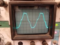
I fed it with square wave today, and there is some oscillation. Below is an example. It looks the same on both channels.
No feedback connected = no oscillation and clean slightly rounded edge. Seems there is little feedback on these amps, the output voltage was maybe double without feedback, so that would be abt 3dB?

I played around with some caps over feedback resistors similar to earlier in the thread, but it did not seem so solve the oscillation, only round the corners more, so I ended up increasing feedback resistors to 20k (less feedback) and it looked almost the same as with the caps, and I also got some extra needed gain since the bluetooth receiver I use seems to have a pretty weak output.
I did some listening again after that, and subjective impression did not change much.
Are the mods shown earlier for stability. I'm thinking the series resistors on the transformers would be easy to try to solder on, if that would help.
I fed it with square wave today, and there is some oscillation. Below is an example. It looks the same on both channels.
No feedback connected = no oscillation and clean slightly rounded edge. Seems there is little feedback on these amps, the output voltage was maybe double without feedback, so that would be abt 3dB?
I played around with some caps over feedback resistors similar to earlier in the thread, but it did not seem so solve the oscillation, only round the corners more, so I ended up increasing feedback resistors to 20k (less feedback) and it looked almost the same as with the caps, and I also got some extra needed gain since the bluetooth receiver I use seems to have a pretty weak output.
I did some listening again after that, and subjective impression did not change much.
Are the mods shown earlier for stability. I'm thinking the series resistors on the transformers would be easy to try to solder on, if that would help.
Sure, I will not fit even if it's quite small. I just wanted to try the concept, and thought it would decrease heat in the main transformer too. It's also nice to have for 'fault tracing' when I have noisy transformers.I would also favor the version with series resistors, unlike a bucking transformer, you can get them in the housing without any problems!
Double voltage is 6dB , it is ok to have minimum NFB possible . But rounded edges at 1KHz means that high frequencies are not ok , Measure sinus at 20KHz vs 1KHz
@Rallyfinnen you mention keeping out HF...
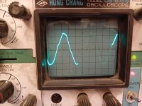
My build of this amplifier is somehow picking up a 20kHz signal. I won't hear it, I guess, but I'm wondering where this could come from. Suggestions? (The input is CH2 in blue, CH1 in yellow is the output, so it's not coming in that way.)
In relation to your other comment, my output signal (square wave below) isn't particularly clean either, but I don't know what to expect. My big Denon integrated amp's output looks better.
Last edited:
Seems like you are using a digital signal for the square wave in the last picture?
That leads me to suspect some disturbance related to you measurement. In the first two pictures, one cannel seems a lot quieter than the other? Are you running dual channel measurements on L&R? What if you swap the channels on the scope on the amp, will it still be the same amp channel with the problem, or does it follow the channel of the scope/generator?
It does not look like oscillation, more like some switching noise or similar? I had an old scope where I got similar disturbance from the switching supply in the scope, now the PS is dead on that scope..
I tried my amp on some 'easier load' 8ohm DIY speakers today, but it did not sound good on the 8ohm taps, 4ohm taps sounded better, especially in the bass. Impedance drops to maybe 6,5ohm at a minimum.
- Home
- Amplifiers
- Tubes / Valves
- Problems with Chinese PP kit