Like this.euro21: Voltage doubler is an interesting idea. You mean like with a couple of diodes and a couple of capacitors?
It's a little bit "overkill", but if you use SS diodes (and lower secondary voltage) it would be cheaper.
It's developed for two box (PSU->amp) design, but can be merged.


6SF5 is basically the single triode in a 12ax7. It is really a poor choice to drive 2a3. It's a wimpy driver.
Now let's see why with some simple math.
1. Let's calculate the 2a3 reactance. Total reactance X = Xc + Xi , where Xc is the capacitive reactance and Xi is the inductive reactance. For sake of simplicity, we will ignore Xi and just consider Xc (however, Xi can be significant in some circuits).
Xc = 1/2(Pi*f*c) = 15915 Ohms. - where f= 100kHz and c= 100pF. Let's just call it 16k Ohms for simplicity.
Why 100KHz? Because if the driver can't drive the Miller capacitance at 100kHz then 10kHz will be phase shifted and distorted.
2. Now we know the reactance, we can do a simple calculation to find out how much current the driver circuit needs:
For 2a3 we would probably like to swing 100V RMS for full power. And we know from the above that that the Reactance required for 2a3 will be around 16k ohms. This means we need 100V/16kOhms = 6,25mA minimum. From personal experience, you should try for 10mA for 2a3.
Your 6SF5 is not going to do this. Perhaps if you don't turn up the volume much then it might sound ok enough though.
You could try to reduce the 2a3 miller capacitance by going for fixed bias instead, but then you need a whole re-design. It's easier to use a solution like a MOSFET follower, or use one of those triode strapped pentodes, or maybe choose an input/driver that has less gain but runs more current, etc.
One nice triode strapped pentode is the D3a. But they are getting pricy. There are a few russian triodes that can drive 2a3 and even 300b, but getting a matched pair of 6C45P-E can be challenging and they are also getting pricy. Maybe you can find some 5842's instead of 6SF5. Gain will be less but the sound will be much better with 5842 running 10mA.
Or go for the MOSFET follower.
Thank you so much for laying all that out, soulmerchant. I appreciate it, and have learned even more now about how extra-sonic frequency behavior affects the audible range. I had never considered it before.
I want to use this procedure to calculate the required input for various tubes, but first -- how did you derive 100pF as c in the equation above? It's not clear to me from the 2A3 datasheet.
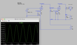
Playing around with the idea of direct-connecting a choke-loaded #10 to 2A3 with a stacked power supply, similar to the Komuro 300B circuit that choke-loads a 6V6 triode driver into a 300B. The operating voltages in this sim check out, but the amplification factor of the #10 is only about 2. In post #415, which had a choke-loaded #10 cap-coupled to 2A3, the amplification factor was 14.5.
Clearly I don't understand direct-coupled circuits yet. 😆
Clearly I don't understand direct-coupled circuits yet. 😆
Attachments
So for the 2A3 the grid-plate capacity is 16.5 pF. The 2A3 input capacity is 7.5 pF. And the output capacity of the 6C6G is 6.5 pF.
To account for Miller Effect of the 2A3, we need to know the 2A3 gain. For a triode power stage, gain depends on the load resistance but for this calc by eyeball I just used G = 3.5. The Miller Capacity is then 3.5 X 16.5 or 57.75 pF.
That all adds up to 71.75 pF, (57.75 + 7.5 + 6.5)pF. Making allowances for strays of wiring capacity conveniently rounds out to ~100 pF. Or 0.1(10^-9) F.
soulmerchant: never mind, I re-discovered the post where jhstewart9 explained how to calculate c.
I thought #10 tube only has gain about 8 according to tube manual. Where did you get 14.5?The operating voltages in this sim check out, but the amplification factor of the #10 is only about 2. In post #415, which had a choke-loaded #10 cap-coupled to 2A3, the amplification factor was 14.5. Clearly I don't understand direct-coupled circuits yet. 😆
Are you sure it's not the overall gain of #10 AND 2A3?
I looked at the two circuits side by side and it baffles me why such discrepancy in gain.

Choke-loading elicits more gain in LTSpice. At least with cap-coupled circuits. A while back I was breadboarding variations of a 6N6 amp using 27 on input. Another member had done the same, with 26 and 27, but he also breadboarded them with plate chokes and measured more gain than when they were resistor-loaded. So it seems to be real. I think it has something to do with the inductive load.
Anyway, given the #10's standard amplification factor of 8, I have no idea why in the direct-coupled circuit it would be 2. My best guess is that it has something to do with the ~680V tension between the 2A3 B+ and the negative leg of the lower PS.
Maybe I'm missing a ground connection somewhere.
Anyway, given the #10's standard amplification factor of 8, I have no idea why in the direct-coupled circuit it would be 2. My best guess is that it has something to do with the ~680V tension between the 2A3 B+ and the negative leg of the lower PS.
Maybe I'm missing a ground connection somewhere.
But BOTH circuits in question are choke loaded and basically identical in DC relationship. It's baffling because the cap coupled circuit SHOULD have tiny bit lower gain since it has a 470K load compared to direct coupled with practically no load.Another member had done the same, with 26 and 27, but he also breadboarded them with plate chokes and measured more gain than when they were resistor-loaded. So it seems to be real. I think it has something to do with the inductive load.
What happens if you place high value caps, like 100uf, parallel with the two supplies for decoupling?Maybe I'm missing a ground connection somewhere.

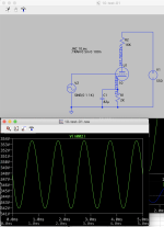
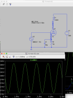
Never mind, I figured it out! I'd incorrectly coupled the inductors in the output transformer with the wrong part numbers in the Spice directive. The primary winding of the OPT was scripted under "K1" to couple with the plate choke on the #10! 🧐
I corrected it and now it works as it should.
A 5V input signal swings 80V on the 2A3 grid. This could potentially work well with that stacked power supply using two rectifier tubes off the second winding, which euro21 shared in post #421 just above.
I guess the question is whether this would sound better than the plate-choke and cap-coupled version, but I suppose there's only one way to find out. 🤓
Attachments

Last edited:
Bizarre! What's the gain with just the #10 input stage by itself with no load, treating it like a preamp? That should tell you if there's any interface issue.
EDIT: just saw your updated post AFTER I hit send!
EDIT: just saw your updated post AFTER I hit send!
Very cool! What I like about this "Komuro style" direct coupled circuit is that the plate choke is also acting as a grid choke for the 2A3's grid, providing a low DCR grid leak to ground or virtual ground.
I think to get more gain to make the amp more "normal" gain. I would like to use a step up transformer instead of an extra tube. UTC A16 with 1:2 step up ratio, 15K:60K, which is not as a brutal of a load for whimpier preamps, unlike a 600R input.
I think to get more gain to make the amp more "normal" gain. I would like to use a step up transformer instead of an extra tube. UTC A16 with 1:2 step up ratio, 15K:60K, which is not as a brutal of a load for whimpier preamps, unlike a 600R input.
Last edited:
Thanks. Yeah this is really fun. An interstage transformer definitely sounds like a good idea. Would love to try one at some point.
I'm about to build a #26 line preamp with Lundahl output transformers and was thinking it might work well to put that in front of the direct-coupled 10-2A3 amp.
10s are just so expensive, though.
Other driver ideas I've been playing with in LTSpice but haven't posted yet:
The 46 and 33 would need an input stage in front of them, if not a step-up input transformer.
I'm about to build a #26 line preamp with Lundahl output transformers and was thinking it might work well to put that in front of the direct-coupled 10-2A3 amp.
10s are just so expensive, though.
Other driver ideas I've been playing with in LTSpice but haven't posted yet:
- 46, cap-coupled and direct-coupled to 2A3 (and 300B) -- certainly more cost-effective than 10 or 10Y
- 33 triode-connected, 130Vak/17mA, both cap-coupled and direct-coupled to 2A3. Rp in triode mode is roughly 6K I believe.
- 5842 at ~145Vak/10mA, both cap-coupled and direct-coupled to 2A3
The 46 and 33 would need an input stage in front of them, if not a step-up input transformer.
No offense @jdrouin, but here we have 22 pages of thread to end up with 3 stages anyway plus some aggravating transformers along the way that are notorious for being unfriendly above 10KHz.
In the end much simpler, better performing and better sounding amplifier could use the modest 6SF5+driver+2A3 in a much more compact unit. Considering a 2A3 amp is a 3W to max 5W amplifier it doesn't sound like heresy to me.
The driver could be different things according to the 2A3 requirements and overall gain without mirror climbing: from a cathode follower if gain is enough to low gain driver with enough current. A true wideband, ultra-low distortion, noise effective input step-DOWN transformer with floating primary (i.e. it goes to ground into the source) could also be used together with lower value than usual, lower noise volume pot, high input impedance and easy to drive for the source. A 3-stage Komuro style amp, as suggested, can be all this.....
Check my post #391 too. 😉soulmerchant: never mind, I re-discovered the post where jhstewart9 explained how to calculate c.
No offense @jdrouin, but here we have 22 pages of thread to end up with 3 stages anyway...
Who said this is the end? 😆
Very likely, nearly everything about single-ended tube amps has already been discovered and the best options well known. At this stage in audio history (not that we're making history), from a pragmatic point of view, the DIYer needs merely to brush up on high school physics -- Ohm's law, Kirchoff's law -- or learn Spice software, gain a functional knowledge of vacuum tubes, and then study the various prevalent circuits, breadboard them, and pick the one(s) that suit their equipment and preferences. So, perhaps the meandering and the backtracking can be a little irritating.
But that's also the nature of personal discovery. We pursue it for its own sake because the journey elicits different kinds of insights along the way that, though they might be tangential to the main quest or repetitions of earlier episodes, enrich it through the ways that everything is connected. In the Great Circuit of Life, why do we listen to the same music pieces, watch the same films, look at the same paintings, and read the same literature over and over again? The answer is different for each person, but in essence it's because part of learning and working on our humanity is to re-evaluate what we've known and done before, and to do it in conversation with others as we teach and learn from each other.
soulmerchant: Check my post #391 too. 😉
Also, after we've learned more, we realize we've missed things in the past and need to go back. 🤣

I am sorry, I really do not understand your thinking. From my perspective, your reply looks more like incomprehensible equipment reviews in magazines. Again no offence. You say one thing and its contrary at the same time. Good luck with your experiments and evaluations.Who said this is the end? 😆
Very likely, nearly everything about single-ended tube amps has already been discovered and the best options well known. At this stage in audio history (not that we're making history), from a pragmatic point of view, the DIYer needs merely to brush up on high school physics -- Ohm's law, Kirchoff's law -- or learn Spice software, gain a functional knowledge of vacuum tubes, and then study the various prevalent circuits, breadboard them, and pick the one(s) that suit their equipment and preferences. So, perhaps the meandering and the backtracking can be a little irritating.
But that's also the nature of personal discovery. We pursue it for its own sake because the journey elicits different kinds of insights along the way that, though they might be tangential to the main quest or repetitions of earlier episodes, enrich it through the ways that everything is connected. In the Great Circuit of Life, why do we listen to the same music pieces, watch the same films, look at the same paintings, and read the same literature over and over again? The answer is different for each person, but in essence it's because part of learning and working on our humanity is to re-evaluate what we've known and done before, and to do it in conversation with others as we teach and learn from each other.
Also, after we've learned more, we realize we've missed things in the past and need to go back. 🤣
Last edited:
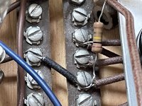
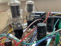
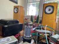
Today I hand-drew the schematic and notes for the direct-coupled 2A3 circuit I’ve been tweaking and listening to for a few weeks. While finishing the drawing and needing a name for it, I racked my brain for something witty from Proust (the necromantic memory of vacuum tube circuit design is vraiment à propos). Françoise, the inimitably funny cook? Léonie, the aunt whose furniture the narrator donates to his favorite brothel? The answer was closer to home in the francophone district of Lewiston, ME.
My great-aunt Lorraine died peacefully last night. It’s no wonder that she was my dad’s favorite aunt. Like the circuit that’s named for her, she was a direct, no-nonsense person whose pithy speech cut to the core of every matter, especially if it was the sort of thing that made other people prim. She would sneak the kids candy before dinner and never lost her mischievous spirit or sharp wit. When I spent some time with her in Maine 30 years ago, I told my brother she was “64 going on 17.” That’s probably why, when my uncle Bubbles died, he generously bequeathed his pornography and sex toy business to Lorraine and my grandmother, her sister Gilberte. My grandmother was mortified, of course, but the shop did very well under Lorraine’s auspices until she was able to close it responsibly.
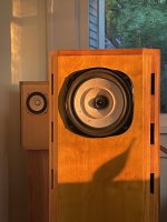
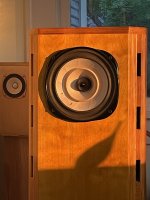
Just as the bumble bee “shouldn’t” be able to fly, this circuit “shouldn’t” sound as exquisite as it does. A paltry 0.55mA of current goes from the 6SF5 into the grid of the 2A3, yet it has an openness and effortlessness that creates a spooky intimacy with small ensemble arrangements. You can hear the musicians’ clothes creaking as their bodies create the music. Probably the high-efficiency Lowther PM6A single full range driver has something to do with that. The circuit is based on the classic Robin/Lipman one from 1947 that Don Garber tweaked for many of his Fi products during the 1990s. Those versions sounded brittle because the 2A3s ran lean at 30-40mA, so I modified the bias and raised the voltage to put them at ~270Vak/52mA for a night-and-day difference. The power supply is 720Vct into a GZ34S, cap-input to a 10H choke, after which the channels split into 2.5H choke each and then the resistor networks and all around higher value caps than in the original designs. I used what I had on hand and would design the PS more purposefully if I do a final build. Like Lorraine, this circuit is imperfect and all about character.
My great-aunt Lorraine died peacefully last night. It’s no wonder that she was my dad’s favorite aunt. Like the circuit that’s named for her, she was a direct, no-nonsense person whose pithy speech cut to the core of every matter, especially if it was the sort of thing that made other people prim. She would sneak the kids candy before dinner and never lost her mischievous spirit or sharp wit. When I spent some time with her in Maine 30 years ago, I told my brother she was “64 going on 17.” That’s probably why, when my uncle Bubbles died, he generously bequeathed his pornography and sex toy business to Lorraine and my grandmother, her sister Gilberte. My grandmother was mortified, of course, but the shop did very well under Lorraine’s auspices until she was able to close it responsibly.
Just as the bumble bee “shouldn’t” be able to fly, this circuit “shouldn’t” sound as exquisite as it does. A paltry 0.55mA of current goes from the 6SF5 into the grid of the 2A3, yet it has an openness and effortlessness that creates a spooky intimacy with small ensemble arrangements. You can hear the musicians’ clothes creaking as their bodies create the music. Probably the high-efficiency Lowther PM6A single full range driver has something to do with that. The circuit is based on the classic Robin/Lipman one from 1947 that Don Garber tweaked for many of his Fi products during the 1990s. Those versions sounded brittle because the 2A3s ran lean at 30-40mA, so I modified the bias and raised the voltage to put them at ~270Vak/52mA for a night-and-day difference. The power supply is 720Vct into a GZ34S, cap-input to a 10H choke, after which the channels split into 2.5H choke each and then the resistor networks and all around higher value caps than in the original designs. I used what I had on hand and would design the PS more purposefully if I do a final build. Like Lorraine, this circuit is imperfect and all about character.
Attachments
-
 BF9CCD15-5004-4C61-A230-DDE4215AD597.jpeg439.1 KB · Views: 192
 -
 87E858C0-53EF-40C5-873D-6874B821926C.jpeg426.6 KB · Views: 304
 -
 94B9435B-E180-47D0-A413-17E9ABF6B9D4.jpeg519.3 KB · Views: 327
 -
 5EFC12C5-132F-44BF-AC66-813FED3A0BBF.jpeg330.2 KB · Views: 293
 -
 8A0E6C97-0B02-4F62-B77C-55F902C69629.jpeg352.2 KB · Views: 185
 -
 F338FA6F-F9FA-4C83-8E59-AA61761EDC20.jpeg403 KB · Views: 174
 -
 99F73496-9226-4818-B02E-B6E1EB7E8C58.jpeg387.1 KB · Views: 181
jdrouin,
Nice pictures, and nice write-up.
I bet it is real good sounding too.
One thing that should be noted:
The 6SF5 has 0.55mA DC current . . .
But a working 2A3 grid in class A1 does not draw any DC current, it only draws AC current due to the grid to filament capacitance, plus due to the (1 + gain) times the grid to plate capacitance (1 + Miller Effect Capacitance).
There is only AC current into and out of the total grid capacitance.
Slew current.
If the 2A3 goes into Class A2, then the load on the 6SF5 becomes too heavy, and we get distortion (Ugh).
I am only trying to make it clear for Newbies who read this very nice thread.
As many have discovered, simple can work surprisingly well.
Last edited:
- Home
- Amplifiers
- Tubes / Valves
- Developing a 2A3 SET