Member
Joined 2009
Paid Member
The cathode follower's distortion performance is mostly about the transconductance of the tube so why not parallel the two halves of the tube for double the gm. The E88CC might offer more gm.Please forgive my attempt at a rough sketch on drawing 45's circuit. I added a bias pot to dial in the bias voltage. It's rough but the concept is in there. I forgot to draw the filament transformer for the 2A3 but you can add your favorite AC or DC supply.
View attachment 1186983
You may want to have a separate heater supply for it too so that you can adequately elevate it above the cathode potential.
The stacked supplies do a nice job of avoiding all that wasted heat from the 2A3 cathode resistor. But, in a directly coupled amplifier that large cathode resistor on the power tube helps to stabilize the dc-operating point. I'm not saying your design is bad, but it's something I'd encourage you to think about further.
Bigun: "I'm not saying your design is bad, but it's something I'd encourage you to think about further."
Not my design. I was just attempting to illustrate the ideas suggested by member 45 in post#450, which itself is a response to one of member jdrouin's DC circuits.
Why you should not put a battery instead of the cathode resistor/cap: https://www.diyaudio.com/community/threads/6sn7-with-fixed-bias.397690/post-7311624Please share "The Trick" about circuit regarding the batteries. Today I use battery bias by placing the battery (+) to the filament pin and the battery (-) to ground. Simple cathode bias. Do you advise a different method?
How to do it: https://www.diyaudio.com/community/threads/6sn7-with-fixed-bias.397690/post-7312309
banpuku,
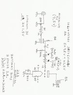
Here is an example of battery bias for a 2 stage SE 2A3 amplifier.
(attached).
Use your favorite driver tube: triode, pentode, or even a true Tetrode (g1, g2, no g3, no beam formers).
Select battery voltages to get the bias voltage you want.
You can adjust the bias voltage in increments of 1.5V (about 1.6V for alkaline cells).
I have used battery bias for 45 tubes, 2A3 tubes, 300B tubes.
I only use self bias now.
The way I connected the batteries, there is no battery current with signal present, unless you turn the volume too high (drawing grid current).
If you make the mistake of turning the volume until the amplifier draws grid current (it clips) . . . you hear the distortion, but do not worry about the small current into the battery . . . it charges it; it does not discharge the battery.
Normally, batteries do not like to be charged, but the current is so small, it does not harm the battery.
I hope that shows you the "trick"
Attachment
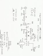
Attachments

I am kind of concerned with signal passing through non-metal (electrolyte) conductor. A conventional battery bias uses either interstage transformer or grid choke.
jhstewart9,
You caught me napping.
Of course, take out the 800R and its bypass cap.
For the past several years, I have always used self bias.
The 800R was a default reflex on my part.
You caught me napping.
Of course, take out the 800R and its bypass cap.
For the past several years, I have always used self bias.
The 800R was a default reflex on my part.
sser2,
My form of battery bias worked very well.
And no, I did not use both battery bias and self bias on the same circuit [jhstewart9 noted my schematic error].
If (you) put a battery from ground to the center tap of an interstage, or from ground to the bottom of a grid choke, then as you say in your Post # 467:
"A conventional battery bias uses either interstage transformer or grid choke."
"I am [you are] kind of concerned with signal passing through non-metal (electrolyte) conductor."
That is exactly what you are proposing as battery bias.
Or, perhaps I did not understand your words.
If that is true, please draw and post two battery bias schematics of what you are proposing, one with interstage, and one with grid choke.
Thanks!
On a similar subject, consider this:
An electrolytic B+ filter cap.
The Signal current flows out of it, kind of like what you said:
"signal [current] passing through non-metal (electrolyte) conductor"
I suppose you do not use electrolytic capacitors anywhere in your amplifiers, right?
Respectfully disagree. The bottom end of grid choke or transformer secondary, which is connected to bias battery minus, is at zero signal potential, so signal is not passing through the battery. Unlike in output circuit, there is no signal current in Class A1 grid circuit other than minuscule current through input capacitance.
Last edited:
sser2,
You are right about my method of battery bias.
Look at my schematic, the battery is in series with the minuscule grid current that you mention.
However, look at what you are proposing:
The bottom end of an interstage transformer secondary, or of a grid choke normally connects to ground.
That means that the minuscule grid current from the grid passes through the interstage secondary or the grid choke to ground.
Then you say to connect the battery between ground and the bottom end of the interstage secondary or bottom end of the grid choke.
Now the minuscule grid current has to travel through the battery.
(just like my circuit too).
As you can see, in both cases, the battery has the minuscule grid current passing through it.
Simplifying:
As you prefer, your series circuit is ground, battery +, battery -, grid choke end, grid choke other end, grid.
As I prefer, my series circuit is ground, grid choke end, grid choke other end, battery +, battery - grid.
According to Kirchoff's rules, these series circuits are equivalent.
Oh, sorry, I forgot the rest of the Kirchoff's series circuit . . . grid, cathode, ground.
I have to ask:
Have you ever measured the series DC resistance of the bias battery (I have).
Have you ever measured the series AC impedance of the bias battery (I have).
Worrying about the series DC resistance and series AC impedance of the battery, versus the minuscule grid current . . .
is just like cutting out the very center of the onion, before you even peeled the dry shell outer layer off of the onion.
I am not going to enter the bias battery impedance, and minuscule signal grid current into some simulation software, to calculate the minuscule change of voltage across the bias battery.
Start designing a good amplifier by taking the outer layers of the onion off first.
There are more important design problems than the minuscule signal current through the bias battery.
Last edited:
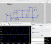
Work has been crazy the last several months, so I've only had time to play with ideas in LTSpice a little bit. Thinking about an earlier suggestion in this thread about stacked power supplies, I mocked up some 2-stage, direct-coupled, choke-loaded designs inspired by the Komuro 300B circuit that's been around for a long time. The idea was to produce enough gain and current to avoid slewing problems when using a 45 or 2A3 output tube.
I have a pair of 6SC7 tubes, which contain two triodes with a common cathode. Each plate has a resistance of 53K. The typical operating point for one triode is 250V/2mA. For A1 audio amplification, the datasheet recommends tying the plates and grids in parallel. So, for the input stage, that would come to 250V/4mA and an effective plate resistance of 26.5K into the grid of the 2A3. Using the plate choke calculation method from earlier in this thread, a 420H choke would be used here. Input sensitivity is about 0.5V, as shown in the attached screenshot.
6SL7 in parallel would net a similar performance, with 250K/4.6mA and 22K effective plate resistance plus a 350H choke (not shown).
Another possibility is to use the same topology with a single section of 6SN7 (or similar -- 6J5, 2C22, etc.), which has a plate resistance of only 7.7K when run at the typical op point of 250V/10mA and 120H plate choke (attached screenshot). Input sensitivity is 2V, which could work with sources like a DAC or CD player.
The 6SC7 and 6SL7 options might work a little better into a 45, while the 6SN7 should be good for 2A3 as well.
I'm intrigued enough by the idea to breadboard the circuits but will have to acquire some plate chokes.
Attachments
I really think you meant UTC A-19 which can handle 8mA DC with 15K:80K impedance, since A-17 doesn't exist in any UTC catalog.A-17 is ideal for this circuit, with its permalloy core it is better than modern transformers with steel cores. A-17 commonly appears on eBay with average price of $150 apiece.
The E88CC is unfit for this purpose IMHO. Plate voltage around 315-320V is too high and even if one might take the risk the plate dissipation will limit the current and in turn gm could likely be equal or worse than the 6BL7 run at 19 ma which should be around 5 ma/V. However the 6BL7 runs in comfort zone....The cathode follower's distortion performance is mostly about the transconductance of the tube so why not parallel the two halves of the tube for double the gm. The E88CC might offer more gm.
You may want to have a separate heater supply for it too so that you can adequately elevate it above the cathode potential.
The stacked supplies do a nice job of avoiding all that wasted heat from the 2A3 cathode resistor. But, in a directly coupled amplifier that large cathode resistor on the power tube helps to stabilize the dc-operating point. I'm not saying your design is bad, but it's something I'd encourage you to think about further.
Can parallel tubes and see if there is any real advantage as the amp is not supposed to drive the power tubes into grid current.
If want to try with high gm tube better to look elsewhere.
Last edited:
A-19 can be used instead of A-17 in a SE circuit. A-19 has a little bit higher step-up ratio.
Even better is UTC LS-40. It is a bigger transformer - higher level, better shielding.
There are also wonderful vintage ITs from Kenyon, K-12, K-21, K-300, K-304. They are functionally similar to LS-40.
All are for 8 mA primary DC current.
The art of Hi-Fi high impedance interstage transformers is lost, nobody makes them any longer.
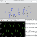
I've been studying Thomas Meyer's well-known circuit that uses paralleled 6N7 @6-7mA and an interstage transformer to drive the 46, which he says is also good for driving 45 and 2A3. On a bike ride today, I realized the 6N7 datasheet says 6-7mA per section, so if you parallel the triodes, you can get up to 14mA of current to put into the grid of 2A3.
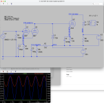
I became curious about choke-loading the paralleled 6N7 with a Komuro-style stacked power supply, so here's a circuit I played with in LTSpice tonight. It runs 6N7 at the datasheet-recommended op point of 294V/7mA per section to get the 14mA of drive current. A 175H anode choke doubles as grid choke for the 2A3, which runs at 250Vak/60mA. Input sensitivity is 1V, so it could be realistic as a 2-stage integrated amp.
The main thing that gives me pause is the very low cathode resistor values. But I'll play around with this some more in LTSpice.
Attachments
- Home
- Amplifiers
- Tubes / Valves
- Developing a 2A3 SET