jdrouin,
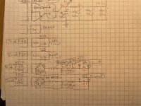
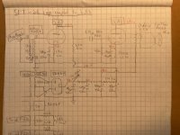
The coupling capacitor that drives the 2A3 grid . . . .
the other end of that coupling cap, needs to connect to the 26 plate, (do not connect the cap to the top of the 26 plate load resistor, that is B+).
Otherwise, the schematic looks very good!
Have fun listening!
The coupling capacitor that drives the 2A3 grid . . . .
the other end of that coupling cap, needs to connect to the 26 plate, (do not connect the cap to the top of the 26 plate load resistor, that is B+).
Otherwise, the schematic looks very good!
Have fun listening!
Oops! That was a mistake in the drawing, which was rushed. The coupling cap is indeed connected to the plate of the 26 correctly.
Sounds like the transformer is OK. The schematic doesn't show a B+ connection for the 26 input stage and its output taken from what conventionally is the power supply terminal. Is that a partial schematic?
edit: answered 🙂
edit: answered 🙂
Yes, it was just incomplete, just to show the topology.
OK, it's fixed now. It turns out I mistakenly added an extra capacitor in the PS that was connected to the 26 plate and shunting the signal to ground.
DOH!
😵💫
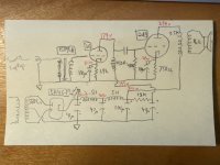
Anyway, here's a full schematic of what's on the breadboard now. Sorry for the sub-par drawings and photos.
It sounds good -- way more gain than is needed -- but there's some 120Hz hum that's probably from the DC filament supply on the 26's or else the HT filtering at the plate -- or both. I'll probably add another 27000uf cap in the 26 DC filament supply. I also detached the input trannies' internal shield, which I need to connect to source return.
The 26's are running right at 150Vak/5mA, the 2A3's at about 245Vak/60mA.
It sounds good so far but I can't turn it up yet because my teenager is still sleeping (at 11:07 am). I hear why people say the 26 sounds "smooth" or "creamy." More authoritative than the previous circuits, though not quite the immediacy of the direct-coupled Fi 2A3 variant I named "Lorraine." I listened to that circuit for more than a year and liked it a lot.
I'll probably tweak this a bit and will move on shortly to a direct-coupled design with a stacked power supply.
Attachments
Last edited:
Love the hand-drawn schematic! I've grown lazy, always use computers tools, should try sometime doing it by hand.Yes, it was just incomplete, just to show the topology.
OK, it's fixed now. It turns out I mistakenly added an extra capacitor in the PS that was connected to the 26 plate and shunting the signal to ground.
DOH!
😵💫
Anyway, here's a full schematic of what's on the breadboard now. Sorry for the sub-par drawings and photos.
It sounds good -- way more gain than is needed -- but there's some 120Hz hum that's probably from the DC filament supply on the 26's or else the HT filtering at the plate -- or both. I'll probably add another 27000uf cap in the 26 DC filament supply. I also detached the input trannies' internal shield, which I need to connect to source return.
The 26's are running right at 150Vak/5mA, the 2A3's at about 245Vak/60mA.
It sounds good so far but I can't turn it up yet because my teenager is still sleeping (at 11:07 am). I hear why people say the 26 sounds "smooth" or "creamy." More authoritative than the previous circuits, though not quite the immediacy of the direct-coupled Fi 2A3 variant I named "Lorraine." I listened to that circuit for more than a year and liked it a lot.
I'll probably tweak this a bit and will move on shortly to a direct-coupled design with a stacked power supply.
About the 2A3 heater supply, it does not look centre-tapped, maybe it could help reduce hum.
Thanks! I turn 48 today and can't be bothered to learn new software programs. The 2A3 filament transformers do have the center tap connected to the cathode resistor and bypass cap, I just didn't have time to draw it this morning. I also forgot to provide the power supply choke values! 2.5H (Hammond 159T) and then 5H (Hammond 158Q). This is just a "draft" circuit anyway.
I did get to turn it up and listen carefully for a while. The DHT driver stage is definitely the most substantial single improvement since the project started. On Sun Ra & Walter Dickerson's "Astro," it brings out the microdetail and inner life of the piano and vibrophone like no other circuit has. It also makes me appreciate anew how sensitive an instrument is the Lowther PM6A.
I did get to turn it up and listen carefully for a while. The DHT driver stage is definitely the most substantial single improvement since the project started. On Sun Ra & Walter Dickerson's "Astro," it brings out the microdetail and inner life of the piano and vibrophone like no other circuit has. It also makes me appreciate anew how sensitive an instrument is the Lowther PM6A.
Last edited:
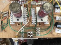
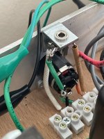
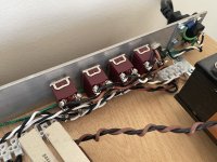
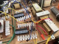
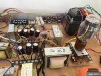
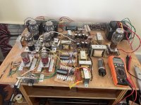
One of the reasons I took a long hiatus was that I needed to build a new breadboard in order to try circuits that require more space. I was finally able to complete it recently, and came up with a modular design based on blocks that fit into a grid of dowel pins. Each block can have whatever is needed -- a tube socket, bank of connectors, potentiometer, poor man's variac, etc.
It has four power switches, a fat terminal block for ground connections, 14 AWG and 12 AWG solid copper ground wire throughout, RCA input sockets front and rear, 8 speaker binding posts, 1/8" and 1/4" headphone jacks isolated from the chassis, and connections for an L-Pad. Note that the volume pot shown by the front input sockets is not currently connected, as I'm controlling volume from the source, a laptop streaming Tidal.
Except for special hardware like standoffs and M3 machine screws, everything was made from material that was already on hand.
Attachments
-
 IMG_5933.jpg591 KB · Views: 148
 -
 IMG_5932.jpg400.1 KB · Views: 133
 -
 IMG_5931.jpg445.3 KB · Views: 124
 -
 IMG_5930.jpg495.5 KB · Views: 125
 -
 IMG_5929.jpg601.2 KB · Views: 125
 -
 IMG_5923.jpg591 KB · Views: 136
 -
 IMG_5922.jpg535.8 KB · Views: 145
 -
 IMG_5921.jpg589.7 KB · Views: 153
 -
 IMG_5920.jpg670.2 KB · Views: 152
Last night I replaced the load resistor of the 26 with a Hammond 156C choke (150H, 8mA, DCR 3.75k) and adjusted the third leg of the power supply rail accordingly. The 120Hz hum is louder, no doubt because of the dramatically increased gain from the 26 and the Hammond 156C, which is not designed as a plate choke. I'll need to add more filtering to the 26 filament supply as well as the HT rail.
However, the sound performance is a noticeable improvement over the resistor-loaded 26. Increased nuance and delicacy at both the treble and bass extremes, as well as throughout the entire frequency range, plus a more palpable spatial presence. Over a very enjoyable couple hours' listening last night, it had an even more relaxed and natural feel than the resistor-loaded version.
Since the next step will use an interstage transformer (Lundahl 1660), which has windings of adequate inductance for the 26, I'll start by using just one side as a plate choke, to see if there's an improvement over the Hammond 156C in that role. And then I'll wire it up for IT configuration.
Schematic with voltage measurements attached.
2A3 -- 250V/60mA
26 -- 168V/5.8mA
Attachments
jdrouin,
How far is the 26 plate choke from the power transformer and B+ Chokes?
What is the orientation of the 26 plate choke coils; versus the power transformer coils, and B+ choke coils?
Is the hum 1 x power mains frequency, or 2 x power mains frequency?
Is the chassis aluminum, or magnetic steel?
How far is the 26 plate choke from the power transformer and B+ Chokes?
What is the orientation of the 26 plate choke coils; versus the power transformer coils, and B+ choke coils?
Is the hum 1 x power mains frequency, or 2 x power mains frequency?
Is the chassis aluminum, or magnetic steel?
It's 120Hz (2x mains freq.) -- a very even and consistent hum. I measure it at 43mV across the 26 filament. I measured the same hum at something like 37mV across the speaker + and - binding posts with no audio signal.
When I turn on the output tubes the 120Hz hum gets louder; when I turn them off but leave the 26 on, it gets quieter but does not go away.
Because of space usage on the breadboard, the 26 filamant transformers are about 10 inches from the main power transformer. They are turned 90* with respect to it, along two axes, though are parallel with each other (again because of space constraints at that particular spot. They are rotated 90* on one axis with respect to neighboring HT filter chokes and the 2.5V AC transformer for the right channel 2A3.
Both channels have the same hum frequency and volume.
There is no chassis; it's an open wooden breadboard with a grounded aluminum flatbar across the back to which I can connect metal items needing chassis ground. At the moment, only the input tranny shields are connected to it. When they're not, you get the angry insect buzz (not the even 120Hz hum that goes through the signal path).
I am having troubles understanding what you are getting for hum.
I am guessing you are using a floating DMM to measure the hum voltage.
A meter that has one end grounded, will pick up hum that is not differential to the two points that are measured.
Do you have 1.5VDC across the 26 filament, and 43mV ripple at 120Hz riding on that 1.5VDC (full wave rectified DC for the 26 filament)?
Did you use a matched pair of resistors from the 26 filament ends, to the 1.9k self bias resistor to ground?
Or, is there a hum pot there, with the wiper going to the 1.9k self bias resistor?
If you remove the 2A3, and connect an 800 Ohm resistor across the output transformer primary,
do you still get 37mV at the output transformer secondary?
If it is 120Hz, that would be coming from the B+ filter choke full wave 120Hz magnetic field.
AC 2A3 filaments, or DC 2A3 filaments?
Are there matched resistors from the 2A3 filament ends, to the 2A3 750 Ohm self bias resistor, or a hum pot wiper to the 750 Ohm self bias resistor?
You did not post a complete and accurate schematic of the 26 DC filament supply, and the 2A3 DC filament supply.
The 26 choke is sensitive to the B+ choke magnetic field (it is 120Hz).
An AC powered filament 2A3 that has imperfect spacing from the filament wires, to the two sides of the plate (4 sides for double plate 2A3), will have 120Hz hum.
2.5A filament wires have large magnetic fields, that will attract to the closest steel plate structure. That causes filament motion, which results in 120Hz hum.
Next: Perhaps ground loops need to be attacked too.
More investigation is required to solve the hum problem cause(s).
Lets work to fix them.
Last edited:
@WntrMute2: Yes, inputs shorted using RCA plugs in which I soldered the hot pin to the return.
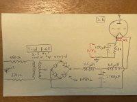
@6A3sUMMER: Thank you for the suggestions about transformer and choke proximity and other matters. It might be easiest to answer your questions with the attached diagram. The 26 filaments are being fed DC by a schottkey diode bridge (1N5822) into an LCL filter using 125uH mini chokes and a 27000uF electrolytic cap.
There is 1.5V DC measured across the 26 filamant pins with a digital multimeter; that is, with one probe on pin 1 and the other probe on pin 4.
The 1.9K (1%) cathode bias resistor and 100uF bypass capacitor are attached to the filament pin that connects to the negative leg of the DC filament supply. During operation there is 11.1V DC from the negative filament pin to ground.
Tonight I moved around the filament transformers, power supply chokes, and anode chokes in order to attain a lot more distance and to orient all neighbors at 90* with respect to one another. I even soldered extensions onto some of the filament transformer primary wires in order to achieve this. It changed nothing in terms of measured or audible hum.
The hum sounds to me like it is being directly amplified from the 26 filament supply -- it's that clean and even.
In my next Mouser order, I'm going to include more of the filament chokes to add an LC stage to what's already there. I bet that will take care of it.
Attachments
Why do you suspect the #26 tube and not the 2A3 as the root of the problem?
Could you try powering the #26 filaments with a battery?
Could you try powering the #26 filaments with a battery?
Disconnect the coupling cap from the 2A3 grid, so that it does not pass any hum from the 26 plate and 26 plate choke.
Do Not remove the 2A3 470k grid resistor.
Is the hum less or the same?
Once we know the answer about the level of the hum with the coupling cap removed, we know whether the problem is before the coupling cap, or after the coupling cap (or in very rare cases, is coming from both places).
Do Not remove the 2A3 470k grid resistor.
Is the hum less or the same?
Once we know the answer about the level of the hum with the coupling cap removed, we know whether the problem is before the coupling cap, or after the coupling cap (or in very rare cases, is coming from both places).
Last edited:
Sadly, 125uH will be little use as a series element. The reactance at 120Hz does not even reach 0.1 ohm. Passive solutions struggle to reach the low noise required for the 26, even as a driver.125uH mini chokes and a 27000uF electrolytic cap.
The 26 is also a very early design, with large electrode spacings that admit electromagnetic pickup, often requires screening of the envelope.
Check out the 26 preamp thread to see how DIYers get around these problems
- Home
- Amplifiers
- Tubes / Valves
- Developing a 2A3 SET

