Well, look at that, I ordered the wrong chokes last year. I'll order the correct ones and then come back to this.
I really need to stop making online purchases without my glasses on.
I really need to stop making online purchases without my glasses on.
Would common mode chokes work in a DC filament filter? It seems they're designed to filter EFI and RF.
The product below is 50mH and has a 2.3A current rating, and also not as expensive as the larger framed ones. A CLCLC filter with these might work.
https://www.mouser.com/ProductDetai...GAEpiMZZMv126LJFLh8y8d6lj%2B5Yqim4Rj2/5OSdkg=
The product below is 50mH and has a 2.3A current rating, and also not as expensive as the larger framed ones. A CLCLC filter with these might work.
https://www.mouser.com/ProductDetai...GAEpiMZZMv126LJFLh8y8d6lj%2B5Yqim4Rj2/5OSdkg=
Just thinking out loud . . .
As it is often used, a common mode filter choke has bifilar windings. The + and - from the rectifiers to the two bifilar windings causes the magnetic fields of the currents to cancel.
The idea is to isolate the rectifiers from the load (just like you mentioned, EFI and RF).
I expect the 2.3A rating is more related to the wire size, than it is to the max current that will cause magnetic core saturation.
The choke has 450milli Ohms (0.45 Ohm).
0.45 x 2.3A = 1.035 Watts, as heat in the wire (if I am interpreting the specs correctly).
Please, will someone verify my theory above?
My 300B brute force 5V 1.25A DC filament supply, CRC, consisted of:
A 6.3V 3.5 Amp secondary, with about 6.5VAC under load
A Schottky Bridge
A 22,000uF cap, followed by a 2 Ohm 20 Watt resistor, followed by another 22,000uF cap.
About 1mV to 2mV ripple, pretty good.
A Brute force DC supply for a 2A3 is more difficult, it needs 2 times the DC current.
Thanks 6A3sUMMER. Given your experiences with the 300B filament, an RC filter with several stages makes more sense than purchasing a component I'm not familiar with. I need to order some resistors to make that happen.
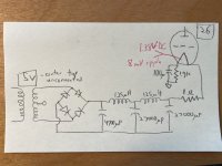
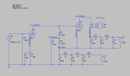
In the meantime, I figured I'd see what kind of filtering I can get with the 125uH chokes, given that successive stages have a multiplying effect. So I added the highest value caps I had on hand. Now, instead of an LCL filter, it's a CLCLC filter with a dropping resistor (attached).
4700uF -- 125uH -- 27000uF -- 125uH -- 27000uF -- 1 ohm
The 26 filament is now running at 1.38VDC (a little low), with a measured 8mV of ripple using the digital multimeter. Quite a bit less than the 45mV of ripple I measured earlier, and the hum is nearly inaudible now (have to put my ear to the driver in order to hear it).
This will certainly do for now, and it hasn't changed the character of the sound.
Attachments
What's the type of the cathode resistor?
There is practically no need power, so even -very- good 0.5-2W resistor can be used here.
I like tantalum resistors (Shinkoh, AN), Z-Foil also very good.
BTW 1k9 isn't typically used value, paralleled 3k9 resistors are more easily accessible.
There is practically no need power, so even -very- good 0.5-2W resistor can be used here.
I like tantalum resistors (Shinkoh, AN), Z-Foil also very good.
BTW 1k9 isn't typically used value, paralleled 3k9 resistors are more easily accessible.
The cathode bias resistor is a 1% wirewound or metal film. I bought it at a local electronics store that didn't specify the type. I've got 1.8K and 2K resistors I could use too, but might have picked this one in part because it matches the color of the Sprague redhead capacitor that also worked at that location. 😆
Attachments
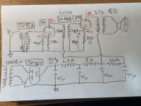
I've now switched from the choke-loaded 26 cap-coupled to the 2A3, to an interstage transformer. It's the Lundahl 1660 wired in the "S" configuration. It provides a slight step up (not needed) of 1:1.125, with 130H on the 26 anode and 146.25H on the 2A3 grid.
I might flip the IT around so that the slight step down would decreased the drive impedance a little, and also provide more inductance on the 26 anode. It doesn't need any of that, though.
26 -- 160V/5.5mA
2A3 -- 250V/60mA
It's difficult to articulate the sonic difference from the choke-loaded, cap-coupled version. Most of the performance is similar: snappy, incredibly detailed, very easy sounding. From the resistor-loaded to the choke-loaded 26, the shift in character was more inward -- it brought out more of the inner life of the music (i.e. the timbre and internal resonance of acoustic instruments, tonal complexity) and had a much faster-sounding response. The IT is a step further in that "inward" direction and I like it very much. It's hard to say, but I think I prefer this even over the choke-loaded cap-coupled version. It has all the benefits of the choke-loaded cap-coupled but sounds more fluid.
I'll tweak the IT version a little and by end of the week will try a direct-coupled design that will require a stacked power supply.
Attachments
Last edited:
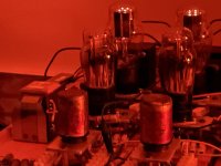
The 26 is also a very early design, with large electrode spacings that admit electromagnetic pickup, often requires screening of the envelope.
Check out the 26 preamp thread to see how DIYers get around these problems
Yes, a shield for the 26 is the right move. I used a pair of aluminium cylinders in capacitor clips. Worked fine.
But I have another question on the subject of using a 2a3. Which is..... if you use AC heating, do you need a hum pot?
I've now switched from the choke-loaded 26 cap-coupled to the 2A3, to an interstage transformer. It's the Lundahl 1660 wired in the "S" configuration. It provides a slight step up (not needed) of 1:1.125, with 130H on the 26 anode and 146.25H on the 2A3 grid. It's difficult to articulate the sonic difference from the choke-loaded, cap-coupled version. Most of the performance is similar: snappy, incredibly detailed, very easy sounding. From the resistor-loaded to the choke-loaded 26, the shift in character was more inward -- it brought out more of the inner life of the music (i.e. the timbre and internal resonance of acoustic instruments, tonal complexity) and had a much faster-sounding response. The IT is a step further in that "inward" direction and I like it very much.
I have a pair of good amorphous core NP plate chokes, 130H. In my case I went back to resistor loading. The sound was more natural and free. The plate choke was a little more closed in with a more wooden piano tone. But I used a B+ of at least 360V, a resistor of not less than 39K and a very good NOS resistor. Under 39K didn't sound good. More would be better still with a higher B+.
I used a LL1660 in step-down with a 10Y and that turned out pretty well. But that wasn't driving a 2a3, it was just as a preamp. Thomas Mayer, who uses a lot of Lundahl iron, only recommended the LL1660 in step-down.
My 26s are not microphonic at all, so I must have gotten lucky. They are National Union brand.
I have not needed to use a hum pot with the 2A3s. For the 45 and 300B, yes absolutely hum pots are needed with AC heating. Using headphones with the 2A3, I can hear a little 60Hz hum. I have a dual gang hum pot from the old breadboard but haven't felt the need for it. In a final build, maybe.
Thanks for your evaluation of the different loading styles, Andy. I'm going to go back and try resistor and choke loading for comparison.
That's partly because someone off-forum pointed out to me that the 26 bias is taken from the midpoint of the filament for AC heating (attached datasheet), which means that with DC heating you have to subtract half the voltage (or, 0.75V) for the load line. The actual bias I had in the previous schematic drawing (10.5V measured at the cathode) was running the tube at close to 8mA, which is off the plate characteristics grid on the datasheet and way too hard on the tube. I've added a dropping resistor and now have around 8.5V on the cathode, which means I'm running it at about 136Vak/5.5mA. It sounds different and I'm not sure I like it so much. So, I'll re-do the different 26 load options to hear the sound with correct op points.
Attachments
For stacked, ensure low ripple and noise at the anode of the lower = first tube.
IME this, when done properly, is … not bad 😉
IME this, when done properly, is … not bad 😉
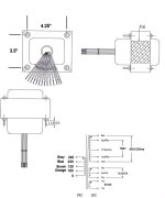
Thanks, yes working on that stacked PS now. This is probably a stupid question, but I’m going to use one rectifier tube and power supply to run the 26 and another rectifier tube and supply to run the 2A3. I have a power transformer with an HT secondary that has a pair of leads for 560Vct and another pair for 300Vct (attached). Can I use the 560V winding to run the 26 and the 300V to run the 2A3?
The center tap should connect to the PS negative, so I imagine that would have to be for the bottom rectifier (which operates closer to ground potential). I’m guessing it would not work because both HT windings have the same center tap and the upper PS would be erroneously referenced to ground.
Just wondering what’s possible and don’t want to hose any components.
Attachments
I use a separate power supply for the 26 as driver tube, but I use Cree 1200V SIC diodes and DC Link first and last caps. In fact I prefer Russian KBG 4uF caps in first position. Even better.
After some more calculating, I'm not going to bother trying to use both HT windings on one transformer. I have two others on hand that I can use with choke-input power supplies, which required different voltages than the PT above. I'm going to start with 660Vct and a 5R4GY to run the 2A3s, and a 190Vct with B-H cold cathode rectifier for the 26s.
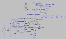
Here's an LTSpice model of what I'm going for. It runs the 2A3 iat about 150V/60mA and the 26 at about 140V/5.5mA.
I've assembled substantial portion of it on the breadboard and plan to start testing it in a day or two.
Here's an LTSpice model of what I'm going for. It runs the 2A3 iat about 150V/60mA and the 26 at about 140V/5.5mA.
I've assembled substantial portion of it on the breadboard and plan to start testing it in a day or two.
Attachments
When the opportunity allows, try R2 plate side of L3 and shift C2 to parallel C4 (or remove it altogether).
If you could find a way to lose C1 without increasing U1 Rp (fil bias) ..
If you could find a way to lose C1 without increasing U1 Rp (fil bias) ..
@J_Perkins : You mean like this (attached)? I'm curious to know your rationale for the suggested changes.
Removing C2 did not affect the voltage or current measurements, so it seems to be unnecessary unless maybe it would have an effect on frequency response.
C1 (26 cathode bypass) was there to increase gain, but removing it from the model has no effect on gain from the 26. Leaving it out would mean lower parts count and, I guess, theoretically more bandwidth, although F3 at that node was set to less than 1Hz. I suppose it can't hurt to remove an electrolytic cap from the signal path, too.
The placement of R2 and L3 (left unchanged here) is intended to choke-load the 26 tube. Are you suggesting that I swap places, to make it resistor-loaded?
Attachments
Removing C2 adds 4k5 to the effective anode load (at all frequencies).
Switching R2 and L3 will help decouple the capacitance of the choke, so long as C2 is removed it is still choke loaded.
R1 at 1k8 will add >15k to Rp, it really needs a capacitor across it. Was meaning to find a way to reduce that resistor value (shunt some current through it).
Switching R2 and L3 will help decouple the capacitance of the choke, so long as C2 is removed it is still choke loaded.
R1 at 1k8 will add >15k to Rp, it really needs a capacitor across it. Was meaning to find a way to reduce that resistor value (shunt some current through it).
- Home
- Amplifiers
- Tubes / Valves
- Developing a 2A3 SET
