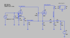
OK, I gave myself a break and breadboarded the Fi X. Actually I started with lower voltage versions just to make sure it was safe, and then got to the point you see here, which sounds the best. The 2A3 is running at about 274Vak/30mA and less than 9 watts. Pretty far below a normal op point.
The attached screenshot shows the signal circuit and voltage readings, which are within a volt or two of what I'm measuring on the board. It sounds pretty good but I need to listen for longer in order to form a stronger impression.
The attached screenshot shows the signal circuit and voltage readings, which are within a volt or two of what I'm measuring on the board. It sounds pretty good but I need to listen for longer in order to form a stronger impression.
Attachments
There appears to be quite a bit of interest in the 10, so here is a first pass that uses three of them.
The performance is somewhat disappointing, with a 1.1V input grid current is reached in the PP 10s.
And only 4.3 watts of audio before losses in the OPT. All even tho I picked a somewhat steep PP loadline for 10s.
To complicate matters, four different DC heater supplies are required for this configuration.
There is a slick fix for that, something I found useful on a project about 20 yrs ago.
Coming to these pages in a couple of days. 👍
A quick look at the PP Class B numbers look impressive until we realize the power gain is only 10 db.👎
Attachments
10/10Y/VT-25 is less usable as output power tube (as driver -especially as DC coupled- it's perfect) due to the less power.
Instead of its usually used (oxide coated filament, larger plate surface and dissipation) VT-25A, mainly as PP amplifier.
See in Thomas site:
http://vinylsavor.blogspot.com/2012/02/tube-of-month-10y.html
20W plate dissipation (thoriated tungsten filament) 801a is an alternative.
Instead of its usually used (oxide coated filament, larger plate surface and dissipation) VT-25A, mainly as PP amplifier.
See in Thomas site:
http://vinylsavor.blogspot.com/2012/02/tube-of-month-10y.html
20W plate dissipation (thoriated tungsten filament) 801a is an alternative.
Last edited:
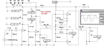
So here we are back in 1938 with a solution that solves a problem in the cct, too many separate filaments to heat,
In this configuration one lead of all the filaments is on common / ground & one low voltage PS, AC or DC will serve the group.
This was a common cct in the late 30s, the back bias was often derived from the DC drop across the resistance of the
loudspeaker magnet winding. This kind of cct could be used with any group of tubes, your choice.😀
The large cap across the bias resistance prevents interstage coupling that would cause the cct to oscillate. 👍
Attachments

I was thinking that, since the 2A3 in the Fi X circuit is running at a paltry 30mA, why not swap in a 45, since that's closer to a good operating point for that tube? So I did that, and used a 5Y3G from a basket of radio tubes someone pulled from a 1938 Zenith behemoth, just to keep the voltage down at first. The 45 is running at exactly 250Vak/25mA and the 6SF5 at 110V/0.5mA. It sounds more relaxed with fuller tonality (less sibilence) than the 2A3 as described above. Also for some reason the 45 circuit is quieter. I prefer this to the 2A3 version of the circuit, though I do think it's worth tweaking the 2A3 to attain a fuller sound. In a little while I'll swap in a 5V4GA or GZ34 to bump up the 45 voltage to 275Vak/30mA and hear the difference.
Sure, the 3.5K OPT is not optimal for this tube, but it sounds good. With a 5K OPT, this circuit might be worth a final build.
While the Fi-based circuit has some drawbacks in tonal development and timbre, it does have very good pacing and there's something understated about the presentation that I really appreciate. The 6SL7 SRPP circuits sound very "forward" in the sense that the music has an assertive (but not aggressive) presence. It's more energetic. With this direct-coupled circuit the music is just kind of part of the air, as it were. Of all the circuits I've tried in this thread, I think I'd rate the direct-coupled at #2, behind 6SL7 SRPP.
OK, that's enough hi-fi babble for now. Will post more impressions later.
Last edited:
Getting a stacked & DC coupled cct to perform the way we want is always a problem.It sounds more relaxed with fuller tonality (less sibilence)
My own preference is the application of a -150V supply so that DC coupling can be achieved with as little signal loss as possible.
Not difficult at all, all the analogue computers of the electronic version did that with ease. The Philbrick Op Amps were a good example.
Sibilence sometimes is an issue with 2-way radio. Especially for Single Side Band (SSB).
It was an issue here for one of our large users of 2-way Radio Test Equipment.
Here is a reference related to HIFI, not SSB.
https://audiophilestyle.com/forums/topic/28770-annoying-speaker-sibilance-and-how-i-cured-it/
I usually solve timber problems with a chain saw, Works every time. 🙂While the Fi-based circuit has some drawbacks in tonal development and timbre,
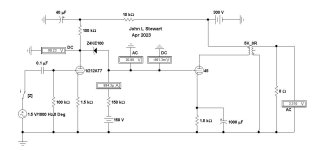
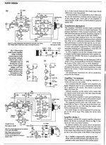
Here is what I had in mind, direct drive to the 45 by way of DC shifting.
In this Sim by a 100V Zener, we used to use selected neon bulbs like the NE2.
Some folks will worry about the Zener noise, that can be minimized by a small cap across the Zener.
The cct depends on a -150V supply but only one mA in this case. Real easy to do when using a common HV CT PT.
And very minimal RC coupled hum filter. I've used neg supplies for many yrs with zero problems. 👍
Attachments
View attachment 1082220
To atone for non-constructive post, here is how I would do a 2-stage 2A3 SET. Driver, triode-connected 57, transformer-coupled to 2a3. 57/6C6 triode has mu of 20 and is quite linear. Due to inductive coupling, gain is equal to mu, and together with step-up interstage transformer, the overall driver gain is 40. Driver is biased with permanently wired 9 V battery, which is better than bypassed or unbypassed cathode resistor. One of the advantages of transformer coupling is driver voltage close to B+ (RC coupling typically only half of B+). Another advantage is low resistance path to 2A3 grid, a safety feature for fixed bias (which has less distortion than cathode bias). Filaments are run on 2.5 V DC with negative side grounded, with CM choke between floating regulator and filaments.
Has anyone tried this topology but with the addition of a MOSFET cascode CCS between the B+ and interstage? Keeping the bias arrangement via the IS secondary. Using a currently-available 1:1 IS transformer instead of a step up. Where the DCR of the IS primary would have to be considered in series with the current setting resistor of the CCS (I assume).
6SF5 is basically the single triode in a 12ax7. It is really a poor choice to drive 2a3. It's a wimpy driver.OK, I gave myself a break and breadboarded the Fi X. Actually I started with lower voltage versions just to make sure it was safe, and then got to the point you see here, which sounds the best. The 2A3 is running at about 274Vak/30mA and less than 9 watts. Pretty far below a normal op point.
The attached screenshot shows the signal circuit and voltage readings, which are within a volt or two of what I'm measuring on the board. It sounds pretty good but I need to listen for longer in order to form a stronger impression.
Now let's see why with some simple math.
1. Let's calculate the 2a3 reactance. Total reactance X = Xc + Xi , where Xc is the capacitive reactance and Xi is the inductive reactance. For sake of simplicity, we will ignore Xi and just consider Xc (however, Xi can be significant in some circuits).
Xc = 1/2(Pi*f*c) = 15915 Ohms. - where f= 100kHz and c= 100pF. Let's just call it 16k Ohms for simplicity.
Why 100KHz? Because if the driver can't drive the Miller capacitance at 100kHz then 10kHz will be phase shifted and distorted.
2. Now we know the reactance, we can do a simple calculation to find out how much current the driver circuit needs:
For 2a3 we would probably like to swing 100V RMS for full power. And we know from the above that that the Reactance required for 2a3 will be around 16k ohms. This means we need 100V/16kOhms = 6,25mA minimum. From personal experience, you should try for 10mA for 2a3.
Your 6SF5 is not going to do this. Perhaps if you don't turn up the volume much then it might sound ok enough though.
You could try to reduce the 2a3 miller capacitance by going for fixed bias instead, but then you need a whole re-design. It's easier to use a solution like a MOSFET follower, or use one of those triode strapped pentodes, or maybe choose an input/driver that has less gain but runs more current, etc.
One nice triode strapped pentode is the D3a. But they are getting pricy. There are a few russian triodes that can drive 2a3 and even 300b, but getting a matched pair of 6C45P-E can be challenging and they are also getting pricy. Maybe you can find some 5842's instead of 6SF5. Gain will be less but the sound will be much better with 5842 running 10mA.
Or go for the MOSFET follower.
Last edited:

The 100pF estimate sounds high, and the 100VRMS is definitely too high, but the general idea that a lot of "slewing current" is needed sounds like a good direction for us all to be moving towards.
All good fortune,
Chris
All good fortune,
Chris
Hi Chris
Ok, lets do the math on this 2a3 miller capacitance:
Cin = Cgk + Cgp*(A+1) where:
Cgk = grid-to-cathode capacitance, composed of the internal tube capacitance plus the stray capacitance
Cgp = grid-to-plate capacitance, composed of the internal tube capacitance plus the stray capacitance
A = stage gain
Cgk = 7.5pF + 1pF stray = 8.5pF
Cgp = 16.5pF + 1pF stray = 17.5pF
A = 4.2
Cin = 8.5pf+17.5pf(4.2+1) = 99.5pF
I think my rough estimate of 100pF is not far off. 2a3 tubes have Bakelite bases, which ADD significant stray capacitances. I measured them. And you can add additional stray capacitance if you use old-school Bakelite sockets. I didn't add that to the above calculations...
Regarding the gain of the input/driver stage:
Just for reference, for 300b you ideally want to swing 140-150V RMS and it's not unusual to hope for 100V RMS to drive a 2a3. Of course you could use less VRMS to drive 2a3 too, and get less power. But my point is that the phase shift and subsequent distortion (in the audible spectrum) will be there with 6SF5.
The other reason I picked 100V RMS for 2a3 is because the OP is probably thinking he can get something like get that with 6SF5. 2.5VRMS in, maybe a gain of 50 or so when using the 100k Ohm load resistor on the plate. It's not unreasonable for the OP to think that.
If the OP goes for an input/driver stage that swings fewer VRMS but runs around 10mA they should be fine. I know because I have built a lot of SE 2a3 amplifier variations. Those tubes/valves I indicated above will all work a LOT better than a 12ax7. Sadly, 5842's are getting kind of rare...
And, as I noted, the OP could stick with the 6SF5 if they used a MOSFET follower set-up. They will need to find one that has low Crss. They could check out TubeLab's postings perhaps for inspiration and advice.
Ian
Last edited:
But, Miller C comes from actual gain + 1 rather than mu + 1 (still, your calc is close enough) and any drive voltage larger than 45 Vpk (= 31.5 VRMS) is into clipping, so not usable. But we really would have a hard time getting too much current drive margin here.
All good fortune,
Chris
All good fortune,
Chris
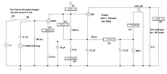
The circuit on p381 clips with only 0.5 v in. That shifts the 2A3 operating point toward cutoff.
In the Sim the 6SF5 cathode bypass has been unhooked so that a One volt signal in works OK.
The input spigot is DC coupled & needs to have a cap to isolate for DC. A one volt DC change at the input causes the 2A3 current to change by 11 mA.
The 490V supply & only Two Watts audio for me is an end to the project. But many others have built this & are happy.
In previous work in these pages a few months ago I found with the 2A3, the drive tube had to contend with up to 200 pF,
2A3 Miller C, 2A3 input C & wiring strays, Add to that the 6SF5 output C, Half of an ECC88 would solve that problem.
The circuit wastes a lot of power, especially in the B+. So the required PS is heavy.
OTOH, many of the circuits we build don't help Global Warming much! 😀
PP versions of this configurations have also been published.👍
Attachments

If your tube amplifier's driver stage has to output a 20kHz signal with peak to peak volts = 2 x output tube's grid bias voltage,
then you are not listening to music.
Just My Opinion
then you are not listening to music.
Just My Opinion
All good points Chris.But, Miller C comes from actual gain + 1 rather than mu + 1 (still, your calc is close enough) and any drive voltage larger than 45 Vpk (= 31.5 VRMS) is into clipping, so not usable. But we really would have a hard time getting too much current drive margin here.
All good fortune,
Chris
This furthers my argument that 6SF5 / 12ax7 is a poor choice. I have even more arguments against 6SF5 / 12ax7 (with its very high output impedance), but maybe that is for another day and another thread.
One thing I did experiment with in the past was to use local negative feedback on 12ax7. This reduced gain and distortion. However it still did not solve the problem with phase shift due to miller capacitance, which is very real. Slew rate is too often neglected...
After fiddling around with 12ax7 I moved on to more powerful triodes with less gain, then triode strapped pentodes. And pentodes and Cascodes. And then other different triodes and triode strapped pentodes.. Oh yes, then somewhere in the middle I tried MOSFET followers and of course started building gyrators after building CCS's. DIY is a great hobby. 👍
In previous work in these pages a few months ago I found with the 2A3, the drive tube had to contend with up to 200 pF,
2A3 Miller C, 2A3 input C & wiring strays, Add to that the 6SF5 output C
I am glad you noted this. If I put all the true 'C' into my calculations (which I do for my own designs) and post it on diy then some people take exception which leads to sometimes ridiculous discussions. Circuit boards can have a lot of stray capacitance btw...
So I post standard equations and plug in the official 'expected' numbers from specs sheets. It's usually enough to convince most people that their design might need a re-think. 😉
Let's have some fun and imagine that real miller C is a significant concern due to all the extra potential sources you note. It's not unreasonable at all. For our calculations we will 'play it safe' and consider it could be as high as 200pF. I have no problem with that.
But then let's take Chris Hornbeck's suggestion that that actual stage gain is much lower, say 2.5 instead of 4.2 - this is indeed a lower power. A 45 tube might be a better choice instead, but we will 'run with it'.
Now let's re-do the reactance calculation:
Xc = 1/2(Pi*f*c) = 7958 Ohms. - Let's just call it 8k Ohms for simplicity.
Then let's calculate our minimum required current to keep phase shift in check at 10kHz
31.5V/8kOhms = 3,9mA
6SF5 / 12ax7 (even with negative feedback applied) is just not going to do it. I know because I tried it. In a 1:1 shoot out, triode strapped C3g running a mere 5mA with same components was in a totally different league.
I then made other designs using other input/drivers and found that 5mA is where things only started to get good. A nice linear input/driver running 10mA was where things started to really get decent (for me at least). And then... MOSFET follower (loaded with CC sink) with much lower output impedance.. way better too.
BTW - 2a3 has higher distortion when it is run cold. This is another topic to consider. It's better to design it for more power.
I think the total of the numbers was not 200 pF but rather we
would need to design for 200 pF to be safe. I'll pull up the Sim later.
And I tried a 6U8 driver, the pentode for gain direct coupled to the
triode as a CF to drive all that C. All in the same bottle.🙂
would need to design for 200 pF to be safe. I'll pull up the Sim later.
And I tried a 6U8 driver, the pentode for gain direct coupled to the
triode as a CF to drive all that C. All in the same bottle.🙂
How do you get 140V RMS for a 300B, with the typical bias being around -60 to - 80V? Is that for A2?Just for reference, for 300b you ideally want to swing 140-150V RMS and it's not unusual to hope for 100V RMS to drive a 2a3
6U8's triode looks like it is made for follower service and the prices for these dissimilar valves/tubs is still very attractive. Thank goodness for that.I think the total of the numbers was not 200 pF but rather we
would need to design for 200 pF to be safe. I'll pull up the Sim later.
And I tried a 6U8 driver, the pentode for gain direct coupled to the
triode as a CF to drive all that C. All in the same bottle.🙂
The circuits with 6U8 I tested earlier in this thread are at pages 222, 241 & 257.
All starts Sep 13. 2022 on Panel 12 of this DIY thread. With lots of real rest data. 👍
All starts Sep 13. 2022 on Panel 12 of this DIY thread. With lots of real rest data. 👍
- Home
- Amplifiers
- Tubes / Valves
- Developing a 2A3 SET