Ok, Im probably mixing things. Let me try to understand. 300B with the grid at - 80VDC relatively to the cathode. The maximum driving AC signal you can supply to the grid while staying in class A is 80V peak (56.57V RMS). How 140V RMS fits here?Hi jcalvarez. Don't confuse DC reference bias with AC signal VRMS.
Nice circuit john. I would use a simple constant current sink with DN2540 instead of the resistor, and run it at 10mA. Still dissipating only 2 Watts or so so should be fine. I see the European equivalent is ECF82, and 6U8 looks similar to 6AN8 too. Lots to love with dissimilar elements in the same envelope. 😉
Hi jcalvarez, you are indeed right. I should have written P-P instead of RMS in post 389. I shouldn't post while sleepy...
Sorry for the confusion. Sadly I can't go back and edit that post.
Also, you can certainly drive the 300b grid positive but as others have previously noted, you need to consider the load on the grid. Low source impedance is a must when you start to even get close to positive grid territory. This is another huge problem with the wimpy drivers.
Ian

Back on page 393 I tried DC coupled to the output. it looked very much like any DC
at the input would shift the operating point of the output. So I moved on to a diff amp,
hoping that might solve some of the other problems.
Here is the result, it got somewhat complicated. But I figured, why not present it here for comment.
Just another of a 1000+ ways to drive a 2A3. 😀
at the input would shift the operating point of the output. So I moved on to a diff amp,
hoping that might solve some of the other problems.
Here is the result, it got somewhat complicated. But I figured, why not present it here for comment.
Just another of a 1000+ ways to drive a 2A3. 😀
Attachments
OK, newbie question from a non-newb, pertinent to the discussion earlier in this thread about driving 2A3 with a 10 or 10Y (à la andyjevans): Does component sequence in the power supply and signal sections matter, given the direction of current flow?
I'd have to think no, since in power supply rails the higher voltage tubes, such as the output tubes, have connections to the PS rail prior to the dropping resistors and connections to the input tubes, which in the signal section are prior to the output tubes. Even though it's standard practice, it has me wondering if that arrangement would create undesirable current loops (i.e. because the current flows in the same direction in the PS and signal sections, yet the component connections are reversed with respect to another).
Now, what if we have a single power supply rail that reverses the standard order so that we can run the type 10 tube closer to the manufacturer-recommended op point of 350V/16mA, which is higher than the voltage used for the 2A3? In this case, the connection to the 10 from the power supply is prior to that of the 2A3, and it also happens to follow the direction of the current flow in the signal section.
In other words, I'm wondering what we think of the attached circuit screenshot from LTSpice (10 at 350V/14mA, 2A3 at 250V/60mA). I think this could sound nice if preceded by a type 26 line preamp w/output transformers.
I've done this for very similar reasons. I built a 45 amp that used Ale Bartola's gyrator boards and wanted max voltage swing capability for that "branch." From there, implemented a couple RC filters (one for each 45) to drop voltage to where it needed to be for the power stage.
The sections are in parallel, so as long as both are active, I don't think there's a "first" and "second" here. It's simultaneous. There may be grounding issues to consider but, again, in my implementation everything worked out fine.
The sections are in parallel, so as long as both are active, I don't think there's a "first" and "second" here. It's simultaneous. There may be grounding issues to consider but, again, in my implementation everything worked out fine.
Thanks for the response. Oh, there's no power supply actually designed yet. I was just noodling with LTSpice to gain a sense of what supply voltages would be needed to run the 10 in the middle of its operating range. Probably that 200uF cap was in an earlier circuit where it made sense.
I tend to like double pi filters with two low-value chokes and caps in series, which is what I'd probably do if I develop a more serious design for this circuit.
I tend to like double pi filters with two low-value chokes and caps in series, which is what I'd probably do if I develop a more serious design for this circuit.
You're gonna have over 14 watts of power heating the resistor R6 and a supply of higher impedance than normal for the output stage.
You're probably better off with a plate choke for the 10.
You're probably better off with a plate choke for the 10.
Last edited:
Is that really a 530V DC supply for the 2A3?
Is this meant to be a Loftin? If so there are some problems.
Is this meant to be a Loftin? If so there are some problems.
You're probably better off with a plate choke for the 10.
That was certainly an idea. How does one calculate the needed inductance in a plate choke?
Is that really a 530V DC supply for the 2A3?
Is this meant to be a Loftin? If so there are some problems.
The 530VDC supply is for both the 10 and the 2A3. The 10 runs at a higher voltage, so the dropping RC section in the PS is to supply the 2A3. I'm also playing around with a direct-coupled variation, which would most likely require a stacked PS, or just completely seperate power transformers and supply circuits (which I think Andy has done).
euro21: Voltage doubler is an interesting idea. You mean like with a couple of diodes and a couple of capacitors?
There are smarter members who can do the math here.How does one calculate the needed inductance in a plate choke?
Thank you!
Just going from datasheet info, the type 10 at 350Vak/16ma has a nominal plate resistance of 5150R. To be -3dB down at 20Hz (-1dB @ 40Hz) would be:
5150 / (2 * pi * 20) = 41H
For -3dB 10Hz (-1dB 20Hz), it would be:
5150 / (2 * pi * 10) = 82H
So, anything from 40H - 100H should work reasonably well.
Here's a circuit using published specs from the Sowter 8901 plate choke (100H/100R DCR). Much more reasonable B+ of 380V, and the 10 is still first in the PS chain. 5.5V input signal drives to full output, as opposed to 8.5V with the plate loaded version.
Very expensive parts!
Attachments
Last edited:
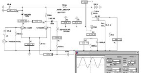
Nice and fast schematic generating there, jdrouin!
You can use similar strategy with plate choke but direct-coupled and have a separate negative supply like this variation of the Komuro 300B circuit. Obviously you need either an input transformer or input cap.
You can use a tube rectifier B+ supply and the negative voltage use solid state diodes for a full wave rectifier from the same AC winding. Naturally the tube rectified B+ will be lower than the diode rectified C- rail. Like this way.
Last edited:
1. Just remember, the distributed capacitance of the 40H to 100H choke, has to be driven by the plate resistance of the type 10 plate impedance, rp. That capacitance might cause the high frequencies to roll off.
Suppose that at 16mA quiescent current in the 10's plate, that it has a plate impedance of 5k Ohms.
Suppose the 40H to 100H choke's distributed capacitance is 1000 pF.
1 / 5k x 2 x pi x 1000 pF = 31.8 kHz at -3db.
But that means that at 15.9kHz the roll off is -1 dB.
But most good plate chokes have far less than 1000 pF; so I would not worry about it.
2. The plate choke will most likely have Air-Gapped laminations, to withstand the 16mA DC.
Be sure to keep the magnetic fields of the power transformer, and the B+ filter choke, from being picked up by the plate choke.
That requires enough distance from the plate choke to the power transformer and B+ choke; Right angle orientation of the plate choke coils versus the power transformer and B+ choke coils, And often a magnetic steel chassis can conduct those fields all the way across the chassis, from corner to corner.
Otherwise, you will get Hum.
Have fun designing, building, and listening.
Last edited:
The 10 in the circuit of page 415 should be loaded with a resistance in parallel with the choke
of something like 20K to smooth out the freq response.
Otherwise there will be a hump at the freq top end. 👍
of something like 20K to smooth out the freq response.
Otherwise there will be a hump at the freq top end. 👍
Y
Don't know why more people don't do that.
Yes, that works very well. Something I've done in particular in several PP amps I've built.👍Naturally the tube rectified B+ will be lower than the diode rectified C- rail. Like this way.
Don't know why more people don't do that.
The Komuro amp minimizes DC offset & drift problems by using a large resistance
in the cathode of the 6V6G so that DC gain is very limited. AC gain is maintained by
the cathode bypass.😀
in the cathode of the 6V6G so that DC gain is very limited. AC gain is maintained by
the cathode bypass.😀
- Home
- Amplifiers
- Tubes / Valves
- Developing a 2A3 SET