Since most attempts to make a good-sounding solid-state guitar amplifier are based around emulating at least some of the characteristics of valves, here are a few images to remind us of the starting point - a single vacuum triode.
I made these images for myself a few years ago, while thinking about the simplest of "toob" guitar preamp stages, the half-12AX7 gain stage Leo Fender borrowed from the RCA tube catalogue, and built into many of his guitar amp designs.
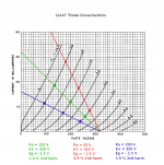
In each case, I've drawn a load-line representing the value of the anode load. Looking at where that line crosses various grid curves, we can see that equal changes in grid voltage do not cause equal swings in anode current. Based on the unequal swings around the bias point, there is a simple formula that can be used to calculate the approximate amount of second-harmonic distortion in each case.
The first image shows the typical Fender / RCA gain stage: 1/2 12AX7, 100k anode load, 1.5k cathode resistor, roughly 320 volts B+. Biased at Vgk = -1.5V, and with a 2 Vpp input signal swing, THD at the output is estimated to be about 2.5%. Audible with a sine wave input, but very subtle.
The low distortion occurs because, inside a triode, the electric fields from anode, grid, and cathode mix, creating unavoidable internal negative feedback.
One side effect of this is that the amount of negative feedback (and therefore, harmonic distortion) varies with the value of the anode resistor. A bigger resistor results in more internal negative feedback, and a more linear triode stage. Gain goes up a bit because of the bigger resistor, but not quite proportionally, because of the simultaneous increase in internal NFB (which reduces gain, opposing the effect of the larger anode resistor).
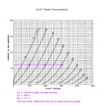
The second image shows the effect of varying the value of the anode (plate) load. As you can see, increasing the 100k load to 200k reduces harmonic distortion. Going the other way and reducing the resistor to 50k, also increases harmonic distortion.
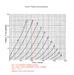
The third image (fig3) shows this taken to an extreme - replacing the anode resistor with a constant current source, with nearly infinite impedance. The resulting horizontal load-line produces extremely low harmonic distortion. No wonder some tube-Hi-Fi aficionados love using constant-current source loads with triode valves in preamp stages.
The fourth image is a "what if" from me, showing the opposite extreme - an anode load of virtually zero impedance. In practice, this could be achieved by using a cascode setup, with the anode of the triode wired straight to the emitter of a BJT, or source of an FET. The output signal would be taken from the collector of the BJT / drain of the FET.
Because the cascode arrangement isolates the triode's anode from signal swings, all internal negative feedback within the triode is suppressed, and the full nonlinearity of the device is exposed. The same 2 Vpp input signal now produces roughly 15% second harmonic distortion at the output, compared to only 2.5% with the typical 100k anode resistor.
For Bucks Bunny - note that 2nd harmonic distortion is not the only one produced by the triodes in these images. But it is the dominant harmonic, and the only one that is so easily calculated just by measuring the unequal signal swings on the load-line.
While the "tube Hi-Fi" guys have taken advantage of CCS anode loads, I have yet to see a tube guitar amp that takes advantage of the opposite end of that same spectrum: a constant voltage source anode load, in the form of a cascode with a transistor, in order to increase harmonic distortion to the maximum possible with a triode. Instead, tube guitar manufacturers tend to be conservative, and make copies of vintage tube amp designs from many decades ago. Their customers tend to be conservative too, and probably most of them want replicas of old "classic" amps, rather than novel new designs.
Heck, I haven't even seen a tube guitar amp that drops the 100k anode load to, say, 56k, in order to gain a little more "tubey" distortion, at the cost of a small amount of voltage gain.
The difference is slight, but audible even with a single gain stage; obviously in a preamp using multiple gain stages, the effect can be cumulative.
Some years ago Fender sold a model they called the Excelsior, which had 220k anode loads on its two-stage triode preamp. The larger value was used in an effort to squeeze sufficient voltage gain from only two triode gain stages.
As an unwanted side effect, that amp also sounded extremely "clean", bordering on the too-clean, sterile sound of a typical solid-state amplifier.
-Gnobuddy
I made these images for myself a few years ago, while thinking about the simplest of "toob" guitar preamp stages, the half-12AX7 gain stage Leo Fender borrowed from the RCA tube catalogue, and built into many of his guitar amp designs.
In each case, I've drawn a load-line representing the value of the anode load. Looking at where that line crosses various grid curves, we can see that equal changes in grid voltage do not cause equal swings in anode current. Based on the unequal swings around the bias point, there is a simple formula that can be used to calculate the approximate amount of second-harmonic distortion in each case.
The first image shows the typical Fender / RCA gain stage: 1/2 12AX7, 100k anode load, 1.5k cathode resistor, roughly 320 volts B+. Biased at Vgk = -1.5V, and with a 2 Vpp input signal swing, THD at the output is estimated to be about 2.5%. Audible with a sine wave input, but very subtle.
The low distortion occurs because, inside a triode, the electric fields from anode, grid, and cathode mix, creating unavoidable internal negative feedback.
One side effect of this is that the amount of negative feedback (and therefore, harmonic distortion) varies with the value of the anode resistor. A bigger resistor results in more internal negative feedback, and a more linear triode stage. Gain goes up a bit because of the bigger resistor, but not quite proportionally, because of the simultaneous increase in internal NFB (which reduces gain, opposing the effect of the larger anode resistor).
The second image shows the effect of varying the value of the anode (plate) load. As you can see, increasing the 100k load to 200k reduces harmonic distortion. Going the other way and reducing the resistor to 50k, also increases harmonic distortion.
The third image (fig3) shows this taken to an extreme - replacing the anode resistor with a constant current source, with nearly infinite impedance. The resulting horizontal load-line produces extremely low harmonic distortion. No wonder some tube-Hi-Fi aficionados love using constant-current source loads with triode valves in preamp stages.
The fourth image is a "what if" from me, showing the opposite extreme - an anode load of virtually zero impedance. In practice, this could be achieved by using a cascode setup, with the anode of the triode wired straight to the emitter of a BJT, or source of an FET. The output signal would be taken from the collector of the BJT / drain of the FET.
Because the cascode arrangement isolates the triode's anode from signal swings, all internal negative feedback within the triode is suppressed, and the full nonlinearity of the device is exposed. The same 2 Vpp input signal now produces roughly 15% second harmonic distortion at the output, compared to only 2.5% with the typical 100k anode resistor.
For Bucks Bunny - note that 2nd harmonic distortion is not the only one produced by the triodes in these images. But it is the dominant harmonic, and the only one that is so easily calculated just by measuring the unequal signal swings on the load-line.
While the "tube Hi-Fi" guys have taken advantage of CCS anode loads, I have yet to see a tube guitar amp that takes advantage of the opposite end of that same spectrum: a constant voltage source anode load, in the form of a cascode with a transistor, in order to increase harmonic distortion to the maximum possible with a triode. Instead, tube guitar manufacturers tend to be conservative, and make copies of vintage tube amp designs from many decades ago. Their customers tend to be conservative too, and probably most of them want replicas of old "classic" amps, rather than novel new designs.
Heck, I haven't even seen a tube guitar amp that drops the 100k anode load to, say, 56k, in order to gain a little more "tubey" distortion, at the cost of a small amount of voltage gain.
The difference is slight, but audible even with a single gain stage; obviously in a preamp using multiple gain stages, the effect can be cumulative.
Some years ago Fender sold a model they called the Excelsior, which had 220k anode loads on its two-stage triode preamp. The larger value was used in an effort to squeeze sufficient voltage gain from only two triode gain stages.
As an unwanted side effect, that amp also sounded extremely "clean", bordering on the too-clean, sterile sound of a typical solid-state amplifier.
-Gnobuddy
Attachments


I realized I could get rid of an op amp and gain partial temperature compensation for the circuit in post #156 by changing the op amp buffer for the rubber diode to a simple emitter follower. With a few value changes, the performance is basically identical.
Anyone see any serious problems with this basic topology?
Anyone see any serious problems with this basic topology?
Attachments

Seems 'sound' to me. How much current is actually running through Q4?I realized I could get rid of an op amp and gain partial temperature compensation for the circuit in post #156 by changing the op amp buffer for the rubber diode to a simple emitter follower. With a few value changes, the performance is basically identical.
Anyone see any serious problems with this basic topology?
So the base current would be about 150 times lower than that, right? would that actually work in practice I wonder?Very little. As shown into a 100k load, it peaks at about 8.5µA. For a 1k load, it's 9.7µA.
I will try the circuit in my simulator, I use LTspice, to play around and understand it better.
I ran a noise analysis and it turns out that the circuit is a bit noisy as shown. R6 is the dominant noise contributor. Changing R4 and R6 to 15k and 1k and V5 to 2.95V improves the noise performance (R2 becomes the dominant noise contributor) and doesn't change the output very much, though it is slightly less accurate. Q4's peak emitter current increases to about 43µA.
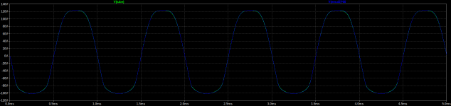
This is what I was working on with the soft limiting (squishy) Jfet stage. The 500K was setup as a variable resistor, which varies the NFB which varies the overall gain and also how much effect the diode limiting has. I posted up the scope pic earlier on this thread. The next step is to string a couple of these stages together and preceded by a standard common source stage with no limiting or very little. Will try it at 18 volts supply, to increase the headroom. For my scope test I used a Jfet source follower as the input for the guitar.

Then you will see that the negative half of the output will clip hard when input signal gets large enough.The next step is to string a couple of these stages together
I hope to keep the signal amplitudes much lower than the 18 Volt supply rail, that's the plan anyways..to avoid a hard clip on the negative going. If it did clip, the second stage is inverted so it should soft limit that excursion.Then you will see that the negative half of the output will clip hard when input signal gets large enough.
In that case your clipping will become symmetrical with H3,H5... dominant instead of H2,H4.If it did clip, the second stage is inverted so it should soft limit that excursion.
There is no free lunch
It may well produce H3, H5 as dominant harmonics at peak signal levels such as the initial pick attack. To me that's okay, I can learn to live with "Fets behaving badly"..as you said there's no free lunch. Once the signal starts to diminish in strength, the H2, H4 start to dominate (hopefully in a gradual way) and finally as the input signal decays down to 100 mV or so it's back to almost no harmonic distortion. I had already built a 3 stage FET preamp, but it was running on a lower supply (9V) and without the diode limiters. It sounded quite good, and the spectrum of harmonics changed with signal strength in a gradual way. I'd like to improve the dynamic range of it by upping the supply voltage and installing the diode limiters on 2 of the stages.In that case your clipping will become symmetrical with H3,H5... dominant instead of H2,H4.
There is no free lunch
Here's my next crazy idea for triode emulation. The last one (post #156) suffers from high noise and very limited input and output voltages. This one does better on both counts. Basically, it's a nonlinear voltage controlled current sink with feedback. The output impedance (scaled down 10x from the tube) is nearly identical to the 12AX7 model.
Attachments
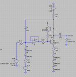

Do you really need the opamp? interestingly, the circuits starts to look a bit like the KMG emulator now. Great minds think alike?Here's my next crazy idea for triode emulation. The last one (post #156) suffers from high noise and very limited input and output voltages. This one does better on both counts. Basically, it's a nonlinear voltage controlled current sink with feedback. The output impedance (scaled down 10x from the tube) is nearly identical to the 12AX7 model.
Only so many ways to skin a cat given the parts we have available to us.Do you really need the opamp? interestingly, the circuits starts to look a bit like the KMG emulator now. Great minds think alike?
This is actually a good thing. I think good guitar amps transition from slightly asymmetrical waveforms at small signal amplitudes, towards nearly symmetrical waveforms when heavily overdriven.In that case your clipping will become symmetrical with H3,H5... dominant instead of H2,H4.
This gives you good "clean tone" for small inputs, and lots of sustain when heavily overdriven.
The change in timbre as the amplifier progressivley shifts from one type of distortion to the other, also mimics what most other musical instruments do - they don't just get louder when played harder, the timbre also changes with dynamics.
For instance, in my Princeton Reverb, the volume control follows the very first triode stage. When the volume is turned well down, only that first stage seems to contribute any audible distortion. It's subtle, but quite audible with any guitar with reasonably strong pickups, even a 'Strat with single-coils. You can make it more obvious by putting a little clean boost between guitar and amplifier input.
At this setting, this is mostly 2nd harmonic distortion, with a small sprinkling of other harmonics.
But if you progressively turn up the volume knob, eventually the class AB power amplifier starts to clip - symmetrically. The amplifier is extremely loud at this point, and since the clipping is symmetrical, there is lots of odd-harmonic distortion in the output.
Leonidas wasn't really thinking about guitar overdrive, but he and the people who worked for him had good ears, and maybe he got lucky, too. His input stage is pretty close to centre-biased, i.e., it was designed to provide lots of clean headroom.
If you look at the schematic of a later guitar amplifier designed to be overdriven - a Marshall JCM 800, say - you can see the designers were thinking about this. The input stage of the JCM 800 ( https://mhuss.com/MyJCM/JCM800_2204.gif ) is biased colder than Leo's input stage, and will make more even harmonic distortion.
The second stage is biased extremely cold, and designed to produce (relatively) large amounts of asymmetric waveform shaping.
The third stage is biased extremely warm, so it tends to squash negative-going output half-cycles.
That very warm-biased third stage is followed by a very warm biased DC-coupled cathode follower, accidentally mis-designed by Leo Fender, that squashes positive-going output cycles because it starts to draw grid current, while the cold-biased stage driving it squashes negative-going half-cycles. So the output of the cathode follower tends to squash both positive and negative peaks of the waveform, moving towards symmetrical squashing and lots of odd harmonics.
There is a lot more going on in this preamp than just one fixed, unvarying, nonlinear transfer function of one fixed curvature. Instead, as signal level changes, there are all sorts of shifts in the type of waveform distortion, along with duty cycle modulation. The end result is a much richer and more musically interesting range of distortion timbres. That's why the JCM 800 family became such legendary rock-music amplifiers. (And then there's the additional contribution of the power amp as it too begins to overdrive.)
By contrast, amplifiers that rely on one fixed, unvarying, nonlinear transfer function tend to produce much more monotonous distortion, that sounds more like a kazoo than a good tube amplifier. It doesn't matter if that transfer function comes from clipping diodes, or the tanh() transfer function of a long-tailed-pair, or the "sigmoid" transfer function Zoom engineers proudly put into their DSP software.
It's the Elizabeth Vigée Le Brun painting vs. the Spider Man comic-book drawings again.
The JCM 800 is old, but it was such a good design that its DNA continued to be present in much newer designs. The inexpensive Laney Cub, for instance, had a preamp that was very similar to the old JCM 800, followed by a much lower-wattage power amplifier section based around a pair of EL84 tubes. Nobody really needs a stadium-filling monster guitar amplifier any more, and I can testify that the Cub got very loud even with "only" 15 watts.
Incidentally, the old and primitive Fuzz Face had some of these desirable qualities; as R.G. Keen put it, "the Fuzz Face is a fortuitous combination of circuits that combine initial soft clipping with asymetrical clipping that changes toward symetrical clipping under drive." ( http://www.geofex.com/article_folders/fuzzface/fftech.htm )
I'm not a fan of the Fuzz Face circuit, and pretty much dislike every sound it makes. Still, one can certainly the Fuzz Face and its endless clones producing duty cycle modulation and timbre variation with input signal level.
-Gnobuddy
I think KMG's use of a string of series diodes and series/parallel resistors, to lower the transconductance of a modern FET to the same value as a vacuum triode from 1946, while simultaneously avoiding accidentally linearizing the FET in the process, was an absolutely brilliant contribution. 👍...the circuits starts to look a bit like the KMG emulator now.
I remember a document on KMG's website where he showed a few predecessors to his eventual circuit, some of which came from other people. I don't recall if the multiple diode series string was KMG's own idea, or he got it from someone else.
But KMG was certainly the man who put all the pieces together - series diodes to shape the transfer function and lower the transconductance, a parallel diode to mimic grid current flow, one source resistor to set the DC operating point, a separate AC-coupled source resistor to set the small-signal gain, high-voltage MOSFETs to preserve the same signal levels and overload margin.
IMO KMG got everything nearly perfect in his 12AX7 emulation, except for the output impedance. Judging from the sound clips on his website, he was able to tweak his preamp circuits to work around that difference.
-Gnobuddy
It needs some kind of buffer, otherwise the input impedance would be extremely low and there'd be constant "grid" current. Could be something other than an op amp.Do you really need the opamp? interestingly, the circuits starts to look a bit like the KMG emulator now. Great minds think alike?
There are definitely some similarities to KMG's circuit. The output impedance of mine is much more accurate due to the feedback, but it has other limitations of course (gain and output swing are the two main ones). I'm basically just trying to figure out what can be done with BJTs and diodes so I can maybe avoid the wide parameter variation you get with JFETs and MOSFETs.
In the non-master Marshall circuits, you get the following progression as you turn up the "loudness" control (assuming constant input voltage around 1-2V pk-pk): Before the power amp clips, you get a mix of H2-dominant preamp tube distortion and H3-dominant push-pull power tube distortion. As the power tubes start to clip, this shifts to odd-order dominant overall. Then the phase inverter starts to clip, which exhibits lots of duty cycle modulation so the even-order harmonics start to come back. Depending on circuit voltages and tonestack settings, even-order harmonics may become louder than odd-order when the PI is driven very hard. Next, the 2nd gain stage and cathode follower start to clip, which causes duty cycle modulation in the opposite direction from the PI, so even-order harmonics are again suppressed. At the top of the control's range, the 2nd gain stage shifts the duty cycle enough for the even-order harmonics to come back.I think good guitar amps transition from slightly asymmetrical waveforms at small signal amplitudes, towards nearly symmetrical waveforms when heavily overdriven.
Fun fact: the volume control for the unused channel increases the DC resistance to ground at V2a's grid as you turn it up. So if you're driving the amp hard enough for V2a to distort, turning that knob changes the bias excursion and therefore the even/odd harmonic balance.
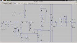
A small contribution to a power amplifier:
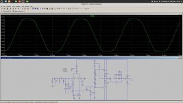
This Amp has no DC at the output and it clips soft. The number of semiconductors is manageable and there is no need to adjust bias. The amp runs in class-b.
It is just an idea, no in reality working amp.
This Amp has no DC at the output and it clips soft. The number of semiconductors is manageable and there is no need to adjust bias. The amp runs in class-b.
It is just an idea, no in reality working amp.
Attachments
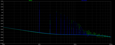
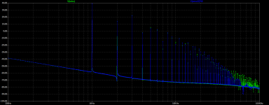
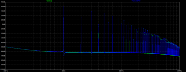
I ran some guitar through LTspice simulating a single 12AX7 gain stage (300V supply, 100k anode load, bypassed cathode resistor, Adrian Immler's 12AX7 model) to see if I could hear the effect of the distortion. With the samples accurately volume matched, I couldn't really hear much of any difference unless I set the drive level so that the (simulated) tube was clipping the transients. Makes me wonder if there's really any point in trying to recreate the preamp tube nonlinearities below clipping levels. Do I have tin ears? I can clearly hear the distortion with a pure sine input.
- Home
- Live Sound
- Instruments and Amps
- Building a SS guitar amp