Folks, I'm kinda butting in here on a thread that I'm a bit out of place on - I'm building an aleph but not this one. Anyway, the question is.... I'm building an aleph 60, and I see from the documentation that the source resistors seem to be indicated as 1R for the aleph 60 but typically lower (0r47) for the aleph 30. I was under the (mistaken?) impression that the source resistors would be the same in both, but I'm obviously wrong. Why is that? Are we just spreading the same current in both amps across more devices? The higher voltage is what gives the higher watt count I think then?
Second - the "front end" is the same I think in all, its just more output mosfets as you go up the scale?
Second - the "front end" is the same I think in all, its just more output mosfets as you go up the scale?
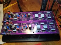
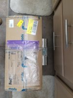
Just finished the circuit boards -- a good day's work. See the attached. Looked up, and right there was the FedEx delivery man with the chassis from HiFi2000. Always works this way, right? (LOL). How do they know I've just finished?
Anyway, he said "there's some weight to these" and, so, I weighed them to see. Right at 40.4 pounds (see attached).
Going to be a busy weekend putting all of this together.
Anyway, he said "there's some weight to these" and, so, I weighed them to see. Right at 40.4 pounds (see attached).
Going to be a busy weekend putting all of this together.
Attachments
Was that addressed to me? If so, don't know about a jumper. If it is needed, let me know. Thanks.You're going without a jumper?
Read the saga of one mkane77g and his ambitions for setting his current gain for the aleph current source...
Yes, put in the jumper. J1 😀
Yes, put in the jumper. J1 😀
IAIMH: Yes, see that now and have the 2.54mm jumpers to make that easy and reversible. Really like those slick parts.
Am going to drill and tap the two chassis first, tomorrow, then fit and install the PSU components, then test them to make sure I'm getting +/- 24 volts. Then can connect the boards to the PCB PSU board and fire them up. Hopefully, no smoke. But you never know, right?
At that point will be going through the calibration duties with my signal generator, multimeter, MV meter, and, if needed, oscilloscope. Haven't read about this yet so know there will be learning involved.
These chassis from HiFi2000 are really well made. Ordered their 2U and 3U heatsink chassis for my M2x builds and the 4U ones are another step up. Plenty of room for the circuit board and should not, hopefully, have any trouble with heat dissemination.
The Digi parts arrived today and got all laid out for the Aleph J 30 build. The Mono PSU PCBs went together in a wink -- here's what they look like (see attached).
Mr. Thatcher seems to have a gift for designing good looking PCBs. A certain symmetry and round versus rectangle theme that works on the visual level. Let's hope that they sound just as good and that I can figure out what the Transformer Center Tap connects to...
Will be doing the circuit boards tomorrow and having all ready for the chassis when they come. Takes a while to get the heatsink drilled and tapped and since there are two chassis, one for each channel, there are two extra, unusued heatsinks. One in each box.
Wonder if:
A) The rectifiers should be mounted on the blank heatsink to reduce temp and,
B) If there is a way to share the heat from the active heatsink to the facing one. A reflective rod, for instance? Probably not the case I think.
But this is one fine build and the design and parts are suggestive of an upcoming success. Hope so!
And, BTW, if there are some of you out there that haven't tried the magnetic helping hand these are sitting on, you deserve to give this a try:
https://www.amazon.com/gp/product/B08QYTYX5H/ref=ppx_yo_dt_b_asin_title_o05_s00?ie=UTF8&psc=1Wouldn't be without one after using it for several months. The 6 magnetic standoff holders are setup so you can turn the board up or down immediately and save so much time and effort you will be using it for every build.
You discovered the secret treasure. Did you get the hint from someone? 😜😜
Only the bold (and foolish) should venture down this road but it's definitely satisfying. I've been conflicted for years as to whether or not to talk about this but in the end, the preservation of others convinces me to stay quiet. So far I have not had any incident. Someone with eagle eyes will spot it.
There's a spot right close to the trimpot P2 for a jumper.Was that addressed to me? If so, don't know about a jumper. If it is needed, let me know. Thanks.

... I just took a closer look and now I suspect you (Cragil59) don't know what I'm rambling about ... just chalk it up to me being crazy ...
Carry on folks, nothing to see here 🙂
2114
Carry on folks, nothing to see here 🙂
2114
Last edited:
Progress Report.
Got the Heatsinks drilled and tapped today and was reminded that it is certainly easier to purchase the Deluxe version of the 4U chassis. Still, am making a number of custom changes to the front and back panels and never mind a morning spent with the drill press.
The first attachment shows the 4U heatsinks after the standoffs have been drilled, tapped and inserted. Then the board is lightly screwed in place (2 screws are fine) so the mosfets can be marked, then drilled and tapped.
You use 2.5mm bits and 3mm taps for these "standard" standoffs and attachment screws. No particular problems here as long as you have some background in drilling through metal and operating a simple tap wrench. The most important item in this first pic is the bottle of BeoLube -- Monsanto's best contribution to the audio world. Makes cutting threads and drilling tough metals a breeze. Important to know that if poured onto a surface it will mask any pencil marks used for location -- so just tap the marked surfaces first with the drill bit to make a small lasting indentation. If you are new to the metal working process, get a drill press first, then assemble cobalt drills. Step-up drill bits are also very handy -- especially if you want to enlarge a power switch hole to 7/8".
The second photo shows the board completed and combined with the 6 mosfets. These take a bit of care to get the leads inserted in the board so they can be soldered. Am using DIY Keratherm and one of these (expensive) pieces will serve for two mosfets if you bend them exactly in half and slice them apart. BTW, you need a 1/8" hole cutter for these to make the screw positioning work and a leather punch is a good choice.
Tomorrow, am going to finish the drilling work with the front and back panel designs. Then it will be relatively easy to finish the assembly and hook all together. The HiFi2000 chassis was ordered with the baseplates and they connect to the heatsink support rails in a straightforward fashion -- but it would have been nice were they able to raise in height as desired for custom wiring and transformer screw space -- you can do this with the baseplates sold for the Galaxy chassis as they affix to the side piece rail slots.
Hoping to have some music from these on Monday; we will see.
Attachments


Hi everybody,
parts are almost odered, but before I do it, I have some - maybe dumb - questions.
I´m building two Aleph 60 monos and now I try to figure out the use of the rectifier&snubber pcb´s.
I have 8 pcs., but as I see - there is no mention in the build guide - I only need 2 per channel for the two rectifier bridges, so 4 pcs. for the two monos.
Am I right (maybe not)? Why are there 8 pcs. in the Aleph 60 dual mono kit?
Rectifier bridge and donut: I would use two 35A/400V rectifiers and a 25+25V/400VA donut per channel, is it okay?
Many thanks in advance!
@Craigl59, great progress, good to see it and good to know how "easy" this build is.
Plott,
That's correct.
On page 13 of the Aleph 60 build guide (V1.0B) is the V8 CRCRC Power Supply schematic (which is recommended for Mono builds). You will see on the upper right side that Randy is accommodating both dual bridge configurations and single bridge configurations (which use the transformer center tap).
For the Dual Bridge configuration, you will need 2 bridge rectifiers per power supply board - this is what I am assuming you are trying to do. The wiring drawing on page 15 is what I would follow.
If you have an extra 4 bridge rectifiers you can save them for another build...
Best,
Anand.
Many thanks Anand!
It was my first thought too, but wanted to be shure.
Any thoughts about the bridge rectifier&donut?

It was my first thought too, but wanted to be shure.
Any thoughts about the bridge rectifier&donut?
From the owners manual:
The Aleph 60 uses 12 computer grade power supply capacitors for 120,000 uF of capacitance and a 600 watt toroidal power transformer.
The Aleph 60 uses 12 computer grade power supply capacitors for 120,000 uF of capacitance and a 600 watt toroidal power transformer.
https://www.passlabs.com/wp-content/uploads/2020/05/a60manr0.pdf
Thank you 007 - the build guide states: "Per Monoblock: Recommend 300VA 25+25 Transformer (example: Antek AS-3225)"
That´s why I´m slightly confused 🤔
That´s why I´m slightly confused 🤔
Thank you 007 - the build guide states: "Per Monoblock: Recommend 300VA 25+25 Transformer (example: Antek AS-3225)"
That´s why I´m slightly confused 🤔
If stereo, 600VA.
Monoblocks, 300VA each. So 2x 300VA.
You could look at a 28+28V transformer if you like, too. I'm working on a 60W Aleph now with a 25+25V and I'm getting 32V rails.
I think I have pair/single heading confused on the GB sheet, so extra Rectifier snubber boards got sent out. You will have extras for your next build(s)!I´m building two Aleph 60 monos and now I try to figure out the use of the rectifier&snubber pcb´s.
I have 8 pcs., but as I see - there is no mention in the build guide - I only need 2 per channel for the two rectifier bridges, so 4 pcs. for the two monos.
Am I right (maybe not)? Why are there 8 pcs. in the Aleph 60 dual mono kit?
Rectifier bridge and donut: I would use two 35A/400V rectifiers and a 25+25V/400VA donut per channel, is it okay?
confirmed: two 35A/400V rectifiers and a 25+25V/400VA donut per channel is OK.
Consider going 27 or 28V if you want, too.
Many thanks Randy, order placedI think I have pair/single heading confused on the GB sheet, so extra Rectifier snubber boards got sent out. You will have extras for your next build(s)!
confirmed: two 35A/400V rectifiers and a 25+25V/400VA donut per channel is OK.
Consider going 27 or 28V if you want, too.
With 28vac the rail would be slightly above 35vdc (?) - would the PSU caps do it or should they be rated higher in this case?
- Home
- Amplifiers
- Pass Labs
- Classic Aleph Amplifier for Modern UMS Chassis Builder's Thread