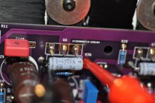
Twisting the AC gain trimpot P2 with leads hooked to an output resistor, R40 doesn't do much. Should AC gain be measured somewhere else? I re-adjuster current to 340mV, down from 425mV.
I'd recommend a hard stop.
I waited a bit to see if someone else would help you... b/c I know I have a different approach than some.
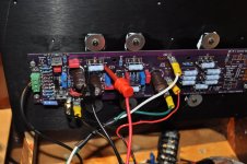
Describe the exact process you're using. Show pics of your signal generator, connections, load resistor being used and the DMMs along with their lead placements.
mV is not a unit for current. 😀 "R40 doesn't do much"? It's a resistor, what do you want it to do? 😀 Again, just playful joking. No ill will.
You're not measuring the AC current gain directly. You need to follow the procedure that Randy so carefully outlined for you in the BUILD DOCS. Show me (us) the pictures from above along with a picture showing that you've filled out each and every one of the blanks properly in the form he created... then I'll help more. If you don't have a printer, recreate it on a piece of paper.
Someone else may be more willing to jump right in. When I asked if you really wanted to do this vs. set and forget, you said you wanted to try it in order to learn. IMO, the best place to start is explaining how you tried to follow the process and what was unclear. Others may have differing opinions. I'm also guessing that you'll be helping out a bunch of other people that will follow in your footsteps by showing what was confusing and how you ultimately did it successfully.
I hope you get it set the way you'd like. You likely had it on the recommended initial setting to begin with. What are you hoping to accomplish by changing it? That is another great place to start learning. What do you think it will do? How much do you want to vary it from the norm up or down? Why did you pick that value? What actually was the original AC current gain for the Aleph Current Source? How will you know if you've achieved the target you'd like? How do you know if that target value is better or worse vs. the initial setting? What have others observed when they altered it?
Seriously, have some fun, but make sure you've got this locked up before you continue turning knobs. Just my

I waited a bit to see if someone else would help you... b/c I know I have a different approach than some.
Describe the exact process you're using. Show pics of your signal generator, connections, load resistor being used and the DMMs along with their lead placements.
mV is not a unit for current. 😀 "R40 doesn't do much"? It's a resistor, what do you want it to do? 😀 Again, just playful joking. No ill will.
You're not measuring the AC current gain directly. You need to follow the procedure that Randy so carefully outlined for you in the BUILD DOCS.
Show me (us) the pictures from above along with a picture showing that you've filled out each and every one of the blanks properly in the form he created... then I'll help more. If you don't have a printer, recreate it on a piece of paper. Someone else may be more willing to jump right in. When I asked if you really wanted to do this vs. set and forget, you said you wanted to try it in order to learn. IMO, the best place to start is explaining how you tried to follow the process and what was unclear. Others may have differing opinions. I'm also guessing that you'll be helping out a bunch of other people that will follow in your footsteps by showing what was confusing and how you ultimately did it successfully.
I hope you get it set the way you'd like. You likely had it on the recommended initial setting to begin with. What are you hoping to accomplish by changing it? That is another great place to start learning. What do you think it will do? How much do you want to vary it from the norm up or down? Why did you pick that value? What actually was the original AC current gain for the Aleph Current Source? How will you know if you've achieved the target you'd like? How do you know if that target value is better or worse vs. the initial setting? What have others observed when they altered it?
Seriously, have some fun, but make sure you've got this locked up before you continue turning knobs. Just my
AC gain / trimpot P2 is the one I'm twisting, one side only. I'm measuring mV @ R30. I'm may just take it apart and set it to it initial value if I can't find a way to measure it.See the Build Doc. What you're looking for is in the Trimpots & Adjustments section and the comments column in the BOM.
For Aleph 30
View attachment 1021574
I reduced current using trimpot P3, measuring the 3w resistors on the current side. All as close to 340mV as possible.
No pictures tonight. It will have to be Wednesday. Nowhere in the build doc does it say where to measure AC gain that I can see. Obvious to some I'll bet.
Amps been on since 6am
No worries, but I have a strong suspicion that you are not measuring it correctly. You might be, but with some communication gaps, we'd best be sure with pictures. Take your time. Have fun. No rush.
https://www.diyaudio.com/community/...modern-ums-chassis.379571/page-4#post-6874343Nowhere in the build doc does it say where to measure AC gain that I can see. Obvious to some I'll bet.
Just as an added precaution... and to make sure you've got the correct document. Please see post #72 and download the Aleph 30 document.
Once again, as I've said - you are NOT measuring the AC current gain directly. It takes a few measurements and a calculation. You are choosing a value that you'd like, then setting it. There is a strong suggestion for what gain to start with in the documents. It's even included in the calculation table Randy created.
Start looking at Page 4. If you do not see the exact header copied below in bold, please let someone know. I'm not going to upload another copy of the document. If you've got the wrong document, then that explains a lot. Perhaps upload the one you used for your build.
AC Gain Setting Procedure
Edited to add - You can search within a .pdf. With a Windows machine CTRL+F is handy or just click the magnifying glass and cut and paste the header from above into the search window.
Edited again to add - I really can't go through every piece of your build, but I'm invested now. 😀 I want to see you do this properly. If you haven't already (cough), I'd strongly recommend installing the jumper. Kinda explains why you weren't getting much of a change earlier if it wasn't installed.
 Remember, if you want to set this yourself, then you have to install header pins of some type and get a jumper cap that you can remove and install. I've been trying to just hint at things to lead you toward it, but I think it's best to just give you some of it.
Last edited:
Looking at page 4. The pcb has an AC gain setting jumper that allows for pulling R21 out of circuit temporarily by removing the jumper.
That jumper has not been installed. I have not figured out how to drive a sine wave into a load, unless it means just gook up a speaker.
I initially had trimpot set to the suggested calc., 428R and this got messed up when I intended to adjust DC offset. I twisted trimpot P2 instead of P1. I need to somehow return it back to its suggested.
value.
Back to the jumper. Doc reads like it should be in place and it is not.
Just read the last 4 lines of your post!!!!!!!!
Thanks for the hint. I woke up at 4:30 this morning dreaming about my problem. My wife and I are headed to the bay area to get her mothers HVAC unit fixed, then to Mt. Tam for a 7-mile hike. Then off to the electronics store. If they don't have any header pins I'll just solder in some wires and let them run wild, twist together when needed. Sounds like a fun-filled day ahead.
Thanks for the hint. I woke up at 4:30 this morning dreaming about my problem. My wife and I are headed to the bay area to get her mothers HVAC unit fixed, then to Mt. Tam for a 7-mile hike. Then off to the electronics store. If they don't have any header pins I'll just solder in some wires and let them run wild, twist together when needed. Sounds like a fun-filled day ahead.
Looking at the board with my optivisor on is see a spot marked AC gain test humper. I suppose this is the spot for the headed pin.
And I read again, Nelson says, with R21 taken out of the circuit ie: when the jumper is installed is R21 essentially removed from the circuit.
And I read again, Nelson says, with R21 taken out of the circuit ie: when the jumper is installed is R21 essentially removed from the circuit.
Last edited:
There's a link in post #66. I've read it a few times. I may just as well re-set the trim-pot. to be continued, Thanks.
Pulling the jumper is the same as pulling the resistor. I figured this out when I had my prototype boards and wanted to twist that pot. Oops. I had a broken de-soldering iron and already installed the resistor. That was why I put the header/jumper in the GB boards. This was inspired by mighty ZM SissySIT where setup includes leaving a jumper out, making a setting, then installing the jumper. Similar idea here.
- hardwire or install jumper / "set and forget"
- pull jumper and play around with settings, then re-install jumper and enjoy. This is for the experimenter.
@mkane77g -
Pulling the jumper (or not having it installed at all) is the same as taking the pot out of the circuit. The fixed resistor is still there. That's why you had some music.
Decide how you want to proceed. I think you have a better understanding now of what's involved if you want to play with this setting. If you're willing to learn... it won't be too terribly difficult. However, if fundamentally you don't know how to put a signal through a load (I had hinted twice that you'd need LOAD resistors and how you might use your signal generator)....
Truthfully, I'd strongly recommend that you:
Set it back to the "set and forget" positions
Install a hard-wire jumper (super easy)
Enjoy the tunes.

Hi guys. Quick intro.
I'm the guy that 'won' Randy's prototype boards in his very generous giveaway. Humbled I am!
I've built plenty of projects from Salas shunt regs, to his DCG3 preamp, Miros Dac and Ian canada streamer goodies. Power amp wise I have been using Dibya/XRK Xmas amp based on tda7293 and also J Lester's tpa3255. Both very nice too.
So I need to crack on to meet Randy's 2 month implementation criteria for the raffle. I dont know what happens if I breach this.....public flogging maybe. Or just 1000 lines..
I must build amps faster
I must build amps faster...
..ad infinitum.
My main 'big ticket' items are heatsinks and trafo/caps. I have found a UK supplier of extrusions. They have a 300x40 and at 150mm tall which is about all I can manage in the rack will give me a spec of 0.48c/w. Or by my maths, using the 106w dissipation per channel a temp rise per channel of approx 50 degrees C.
Do you think this is acceptable?
If I can squeeze a 400x40 in and still at 150 tall I can achieve 0.36c/w which gives a rise of about 38C.
This is assuming the heatsink orientation is the correct up/down. I could use a 160mm section cut to 300mm meaning the fins run front to back but then attach small 40x40 fans to the rear edge....makes for a fan heater too!
Cheers
James
Last edited:
I had an epiphany last night while sleeping. 'Instead of removing the board from the heatsink to re-set the P2 pot to 428 wouldn't a measurement at R21 that shows 820 tell me it set. 428+392=820. Or, what about measurement at the jumper position? Trying to be quiet while my wife sleeps. It will be a while.
Hi guys. Quick intro.
I'm the guy that 'won' Randy's prototype boards in his very generous giveaway. Humbled I am!
Wooooooooooooooooo! Congratulations.
My main 'big ticket' items are heatsinks and trafo/caps. I have found a UK supplier of extrusions. They have a 300x40 and at 150mm tall which is about all I can manage in the rack will give me a spec of 0.48c/w. Or by my maths, using the 106w dissipation per channel a temp rise per channel of approx 50 degrees C.
Do you think this is acceptable?
Emphasis added into your quote is mine.
Let's first assume that the dissipation spec is accurate and has already been de-rated for the dissipation you'll be using (it likely is not). What's your ambient temperature in your room? What's 50C plus the ambient temperature in your room? Is that OK for your fingers / animals in the house? Is that OK for the output devices?
tl;dr - ZM posted some really nice rules of thumb earlier in the thread re: the Modushop 40mm heatsinks / chassis sizes. You can compare sizes to the ones available to you for a better idea of how much heatsink you'll need.
Cheers and Congrats!
All dreams can't come true. I removed the board and re-set the trimpot to 428. Measuring V now. Interesting the decline of the value as things stabilize.I had an epiphany last night while sleeping. 'Instead of removing the board from the heatsink to re-set the P2 pot to 428 wouldn't a measurement at R21 that shows 820 tell me it set. 428+392=820. Or, what about measurement at the jumper position? Trying to be quiet while my wife sleeps. It will be a while.
Thanks to all the help I added a star under my username.
Attachments
Last edited:

That works out ~2.1A per rail - right on the money. And really nicely spread across the MOSFETs - the matching worked!Volts measured.
As a wise builder (6L6) has told me in the past, if it's working as it should, time to screw the top on and enjoy it.
- Home
- Amplifiers
- Pass Labs
- Classic Aleph Amplifier for Modern UMS Chassis Builder's Thread