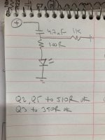
I noticed a similar one time pop in an amp that was oscillating. If you have an oscillation tester, this would tell you if that monoblock was passing high frequency AC to the speakers. Sorry, I don't have a schematic handy.
somewhere intermittent connection
soldering joints yada yada , you know the drill
so, everything is suspiciosssssssss
soldering joints yada yada , you know the drill
so, everything is suspiciosssssssss
Zen Mod: Know the drill but didn't consider solder joints (visually checked) because the board only does it once. Can an intermittent connection cause a single pop?
Have had
no harm in checking do you have mounted 1nF caps in two positions, and - if you have, no way it's oscillating
also, no harm in mounting them as prevention
post pics and your ref. schm
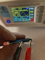
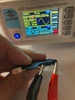
It's something you can build cheap and easy. Someone somewhere on this forum once described a test circuit in words. Here's a working schematic & the device in action (the LED lights up when AC above 50kHz at greater than 5V p-p is present, but this probably depends on the on-voltage of the LED you use). Ignore the text referring to transistors, it's from a troubleshooting effort.@ranshdow Have had no prior experience here and will have to do some investigating on oscillation testers. Always take the approach of turning a weakness into a strength and if the project lets you buy new equipment, then it's a good one...
Attachments
Last edited:
Bad News.
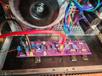
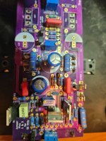
Took the PCB out and reflowed all of the Mosfet and Resistor joints. This board had a problem originally because the 112 Mosfets/resistors were incorrectly placed in the 111 slot. They were relocated and all of the resistors and mosfets replaced. After this, the PCB worked fine but with the POP noise.
After reflowing, turned the unit on with the MM set to measure the DC Offset. It turned on and showed a typical value of -0.004 vdc or so.
THEN after a minute or two, the offset jumped up to 18-19 VDC and could not be adjusted by the trimpot.
Woe is me! It was working with the pop for some time. But after the reflow, it is not operative.
Any ideas? Otherwise will have to build another board and my parts and equipment are in the mountain home.
Jpegs added.
Attachments
just replace all smaller actives, see where that is leading you
meaning small bjts, diodes, zeners, TO220 mosfets
that's cheap and fast
probably certainly faster than proper deduction process
meaning small bjts, diodes, zeners, TO220 mosfets
that's cheap and fast
Checked the Mosfets and three (!) are completely shorted out. Am giving up on this PCB entirely and replacing it with another.
In a "popish" kind of way it sounded good while it ran...
In a "popish" kind of way it sounded good while it ran...
having proper large format washer and split washer, on mosfet screw.......... is proper way of doing it
maybe that was a culprit, maybe wasn't
but, if everything else was proper, you have it
maybe that was a culprit, maybe wasn't
but, if everything else was proper, you have it
Think not ZM. Used those connectors for some time and the tightness is always modest. My guess would be that some active board item was distressed when the Mosfets were in the wrong locations and that has became worse causing the failures.
But its irrelevant. Am replacing everything next May.
Until then, can use the 300B and A/B amps here in place.
But its irrelevant. Am replacing everything next May.
Until then, can use the 300B and A/B amps here in place.
never underestimate heat-cycling and effects of same; depending how good screw-tapping is made in heatsink itself, you can have un-tighten screws in no time
not saying that it was culprit 158%, more preaching for future times


not saying that it was culprit 158%, more preaching for future times
Hmmm.... I think you have other problems there as well.Checked the Mosfets and three (!) are completely shorted out. Am giving up on this PCB entirely and replacing it with another.
In a "popish" kind of way it sounded good while it ran...
Shorted MOSFETs would cause an immediate swing to V+, or V- rail measured at the speakers' positive terminal, as soon as you turn the power ON.
If the MOSFETs pair (V+ rail to V- rail) are shorted, the mains fuse should (well, one would hope so...) pop out/blow.
Pass DIY Addict
Joined 2000
Paid Member
I see a PCB with a ton of solder flux that needs to be cleaned off. I also see heatsinks with lots of scratches and/or debris that might interfere with silpads that are very thin and easy to puncture.

Pass DIY Addict
Joined 2000
Paid Member
Ah, from the image, I can't tell what is on the sink, if it just "looks" like there is something there, or if there are places of raised relief that might contribute to a problem. When I'm done with a PCB, I take a fine tipped flat blade screwdriver and physically scratch between all of the solder pads just to make sure there are no inadvertent (and very nearly invisible) solder bridges left behind. I've had a number of problems in the past and like to try to eliminate as many potential problems as possible. Just tryin to be helpful.
In the end, redoing the board is a good approach. One of my Aleph-X amps lost a power supply rail when a diode bridge burned and it caused a problem on the PCB. I didn't find the problem until I had fully depopulated the board. Turned out that when the bridge burned, it also burned a ground trace on the bottom of the PCB.
In the end, redoing the board is a good approach. One of my Aleph-X amps lost a power supply rail when a diode bridge burned and it caused a problem on the PCB. I didn't find the problem until I had fully depopulated the board. Turned out that when the bridge burned, it also burned a ground trace on the bottom of the PCB.
Eric: yes use the screwdriver approach on this and other boards. Also, clean the solder side with alcohol with a toothbrush. Technique was never a problem with this board. Placed the 2nd Mosfet set in the wrong slots and it caused terminal problems. The pop the board made upon heat up has not been identified.
- Home
- Amplifiers
- Pass Labs
- Classic Aleph Amplifier for Modern UMS Chassis Builder's Thread