mkane77g - Wooooooo! Time for some Whistle Pig (I think that was one of your favorites from when you were building your AJ).
^^^^^^^^^^^^^Thanks. I've moved on from Whistle Pig. I was enjoying an Oregon whiskey, but the bottles empty. I have backups.
Heatsink hot spots are still 51°C. Not sure if it's my imagination but this amp seems to have smoothed out a bit after 20hrs. run time. Could it be because the jumper is now in place? We've been playing acoustic guitar all morning and it's showing some delicacy, even at low volumes. We use dipole H frames for bass with their own amps, so the Aleph 30 just takes care of mid's and tweets.
I'll throw something different at it in a while and twist the volume a bit.
Attachments

Last edited:
Am just getting all of the parts for an Aleph J 30 build and have only one item remaining -- and it is embarrassing, I guess...
Cannot find a lighted on/off switch that will work for the HiFi2000 chassis selected. Would prefer a larger, round lighted switch and it can be latching or momentary as long as it shows the power state (on/off). Have tried Sydien and Quentacy switches from Amazon and the Quentacy suffer from led failure when used as a 120 volt switch.
Have poured over Amazon, Mouser, and Digi lists and can find nothing ideal. Hoping the sage pundits here have an easy choice that they use frequently. Thanks and sorry for the simple nature of this question. Would not ask if long online searches had not yielded a switch.
Will be starting the board build tomorrow and, hopefully, finishing up the monoblocks sometimes next week. Will depend on the chassis that are delayed in Paris -- has happened to me more than once. Have a Rigol signal generator and look forward to learning and applying the tuning instructions detailed above. Nothing like a new build to get the blood flowing, right?
Am just getting all of the parts for an Aleph J 30 build and have only one item remaining -- and it is embarrassing, I guess...
Cannot find a lighted on/off switch that will work for the HiFi2000 chassis selected. Would prefer a larger, round lighted switch and it can be latching or momentary as long as it shows the power state (on/off). Have tried Sydien and Quentacy switches from Amazon and the Quentacy suffer from led failure when used as a 120 volt switch.
Have poured over Amazon, Mouser, and Digi lists and can find nothing ideal. Hoping the sage pundits here have an easy choice that they use frequently. Thanks and sorry for the simple nature of this question. Would not ask if long online searches had not yielded a switch.
Will be starting the board build tomorrow and, hopefully, finishing up the monoblocks sometimes next week. Will depend on the chassis that are delayed in Paris -- has happened to me more than once. Have a Rigol signal generator and look forward to learning and applying the tuning instructions detailed above. Nothing like a new build to get the blood flowing, right?
Can you provide some more details about what exactly you are looking for? Are you using a soft start module like MJ's PCB which accepts either momentary or latching? How big is the hole on the front panel? 16mm, 19mm, 22mm ?
Have you tried the usual suspects like Ulincos or Apiele? I don't seem to have any trouble finding push button latching or momentary switches on Amazon (more momentary options than latching):
https://www.amazon.com/dp/B071CNX3CF/ref=twister_B071QWGMG9?_encoding=UTF8&th=1
Here's a latching version:
https://www.amazon.com/Ulincos-Latc...6&sprefix=Ulincos+latching,aps,96&sr=8-3&th=1
Both of the above are safe to 250VAC per the manufacturer.
Have you tried Bulgin? Like Bulgin MPI002 series? This can ONLY be used at low voltages however (not 120VAC), i.e. you will need a low voltage On-OFF switch module (MJ's PCB, AMB's e24 circuit, Neurochrome ISS, etc...):
https://www.mouser.com/ProductDetail/Bulgin/MPI002-28-BL?qs=xh6E4zEJdPkOtVBIXypxjQ==
IMHO, with any toroidal transformer that is larger than 400VA, which many of these larger Aleph amplifiers require, I would recommend a soft start circuit along with a low voltage supply which addresses each issue separately. I personally prefer and use Neurochrome's ISS.
But I'm not a sage pundit.
Best,
Anand.
Last edited:
Anand: Thanks for the response. Yes, looked at all of those and the Ulincos is 12volt DC, not 120volt AC. The Bulgin is 24VDC. If these can also be used for 120Volts AC, then let me know.
I am using the Quentacy that is rated for 250VAC and it works but the leds dim out over a couple of hours and then stay dim -- so much so that you cannot use them as an indication of the power being on. They appear to be burnt out by the AC voltage.
Here are other details:
1. Any round hole size up to 7/8" is fine. Use 3/4" for the Quentacy. Drill these myself.
2. Want to wire the L and N of the incoming IEC to the switch, then pass that to the transformer.
3. Am using 200VA transformers, one for each board as it is a mono build.
4. No soft start module is planned at this time.
Thanks all. Again, have looked in many sources and have only found non-lighted toggle switches that do the electronic connections easily. Lighted switched that are rectangular (have 4 from Amazon) are OK but the mounting rectangle is difficult to cut and requires extreme precision for those switches that snap in to lock.
@Craigl59
Look at my first link, scroll down to Product Description and then scroll down to Specifications. It says “Switch Rating: 5A/250VAC”. Sometimes they list 12VDC but that usually should be the LED rating. There should always be a separate switch rating or else I don’t purchase the switch, especially for AC switching applications.
I use the Ulinicos model in a few of my amps where I need to switch directly from 120VAC, haven’t had an issue that you describe. It sounds like you have a defective switch to be honest. That being said, I have only used these types of a switches on smaller amplifiers. One is a MOFO (with an SMPS supply), and the other is a Class D amp which idles at <10 watts and also uses an SMPS supply.
The Bulgin is only meant for low voltage supply switching, so you will need something like the AMB epsilon 24 board. I have used that board in several builds with momentary type vandal switches, such as the Bulgin. This might be worthwhile for you so you are not restricted by some switches that have a low AC voltage rating (like some of the Apiele‘s I have seen).
I have moved on to RGB capacitive switches now from Schurter but they are far more expensive and require some special circuitry to work right; they also need a low voltage supply (I.e. 5V to 28VDC), and are not rated for AC switching. Most of the fancier switches I have seen need a low voltage supply…period.
Best,
Anand.
Thanks again, Anand. My concern with your Ulinicos switch is that it the LED will fail with 120VAC input just as my Quentacy switches have. Also have a Sydien 110V switch that just arrived and will try that tomorrow to see if the LED portion continues to operate once connected to AC.
Surprising to me that something as simple as a power switch should generate a need for additional circuitry but am not knowledgeable about electronic design and only try to find the right part for a specific need.
Surprising to me that something as simple as a power switch should generate a need for additional circuitry but am not knowledgeable about electronic design and only try to find the right part for a specific need.
@Craigl59
Something else that may not be obvious are the surge currents involved when switching 120VAC with a larger toroid and banks of capacitance. Something like 50-100VA is no problem. But when we are talking about larger VA’s the surge currents can potentially be in the many hundreds of amperes (particularly with the HUGE capacitances used in Class A amplifiers), at which point the switch can arc and burn out. I suggest you read up on this. MJ touches upon it in the link I sent you but Tom Christiansen of Neurochrome illustrates the problem with both measurements and mathematics. So it isn’t as simple as it appears. The charts are very illustrating of what really is going on even for a few milliseconds! Moreover with regards to these Amazon push button switches, many of which are only rated to 5A maximum and that may be completely inadequate. Looking at the non illuminated Schurter power switch modules (similar to what the DIYAUDIOstore provides) - they are rated at 10A/250VAC, but with massive dielectric ratings as well (in the kVA’s!).
The other thing to realize is that safety and reliability are extremely important imho. As such, I end up using a soft start with these Class A amplifiers with huge capacitances (or at least a CL60 thermistor) and do the same with my Class AB builds as well. Thankfully, the SMPS supplies I have used have integrated softstarts and surge protection built in.
Good luck in your search and report back with your discoveries!
Best,
Anand.
Last edited:
Anad: Have decided for this build to simply go with a toggle switch and if lighting is required, will use one of the LEDs off of the circuit board. Used a Cl60 thermistor on the two PSUs I built for the M2x (outboard power supplies) and know how to implement them. Randy's PSU boards have a place for them as TH1-2 so they will already offer that protection. BTW, the Ulincos switches take 2 months to arrive off of Amazon -- they are slated for early April delivery.
Speaking of circuit boards, the BoM for the Aleph J 30 found in the most excellent Build manual (thanks, rhthatcher!) lists the 0R47 3W as R22-27 and R36-43. This is for 14 resistors, 28 for a stereo set. But the count specified is for 12 and 24. Assume the difference is the unpopulated R37 and R41 surrounding the unused Q7 and Q11. But correct me if I am wrong here.
And good news in that the chassis ordered for this build may arrive as early as Friday! No long delay in Paris this time.
Last edited:
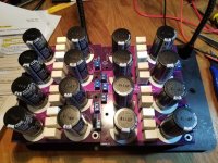
The Digi parts arrived today and got all laid out for the Aleph J 30 build. The Mono PSU PCBs went together in a wink -- here's what they look like (see attached).
Mr. Thatcher seems to have a gift for designing good looking PCBs. A certain symmetry and round versus rectangle theme that works on the visual level. Let's hope that they sound just as good and that I can figure out what the Transformer Center Tap connects to...
Will be doing the circuit boards tomorrow and having all ready for the chassis when they come. Takes a while to get the heatsink drilled and tapped and since there are two chassis, one for each channel, there are two extra, unusued heatsinks. One in each box.
Wonder if:
A) The rectifiers should be mounted on the blank heatsink to reduce temp and,
B) If there is a way to share the heat from the active heatsink to the facing one. A reflective rod, for instance? Probably not the case I think.
But this is one fine build and the design and parts are suggestive of an upcoming success. Hope so!
And, BTW, if there are some of you out there that haven't tried the magnetic helping hand these are sitting on, you deserve to give this a try:
https://www.amazon.com/gp/product/B08QYTYX5H/ref=ppx_yo_dt_b_asin_title_o05_s00?ie=UTF8&psc=1Wouldn't be without one after using it for several months. The 6 magnetic standoff holders are setup so you can turn the board up or down immediately and save so much time and effort you will be using it for every build.
Attachments
The Digi parts arrived today and got all laid out for the Aleph J 30 build. The Mono PSU PCBs went together in a wink -- here's what they look like (see attached).
Mr. Thatcher seems to have a gift for designing good looking PCBs. A certain symmetry and round versus rectangle theme that works on the visual level. Let's hope that they sound just as good and that I can figure out what the Transformer Center Tap connects to...
Will be doing the circuit boards tomorrow and having all ready for the chassis when they come. Takes a while to get the heatsink drilled and tapped and since there are two chassis, one for each channel, there are two extra, unusued heatsinks. One in each box.
Wonder if:
A) The rectifiers should be mounted on the blank heatsink to reduce temp and,
B) If there is a way to share the heat from the active heatsink to the facing one. A reflective rod, for instance? Probably not the case I think.
But this is one fine build and the design and parts are suggestive of an upcoming success. Hope so!
And, BTW, if there are some of you out there that haven't tried the magnetic helping hand these are sitting on, you deserve to give this a try:
https://www.amazon.com/gp/product/B08QYTYX5H/ref=ppx_yo_dt_b_asin_title_o05_s00?ie=UTF8&psc=1Wouldn't be without one after using it for several months. The 6 magnetic standoff holders are setup so you can turn the board up or down immediately and save so much time and effort you will be using it for every build.
The center tap connection came about when I did an amp restoration that had a center tapped transformer. If you're using a standard Antek or similar with 2 bridges you will not be using that center tap connection.
Nice pick using the screw terminals! The idea with those PCB footprints is they're good for QD spades, bare wire, or screw terminals. Pick whichever flavor you prefer.
How did you like working with the tall 5W resistors?
The rectifier on the chassis floor is fine, no need to mount it to the heatsink.
What chassis did you get? I imagine you'll simply end up with an unused heatsink per amp. Gianluca is supposed to have a mono chassis option available any day now.

The tall 5W resistors were easy to work with if you use a simple technique: Place them all in their slots, tack them with tape just strong enough to turn the board over then allow them to provide a level support for the leads all on their own -- leads can then then be soldered 'en toto' and all will stay in place and be tight. The same technique is used for the screw terminals as they have a tendency to drift and not seat completely.The center tap connection came about when I did an amp restoration that had a center tapped transformer. If you're using a standard Antek or similar with 2 bridges you will not be using that center tap connection.
Nice pick using the screw terminals! The idea with those PCB footprints is they're good for QD spades, bare wire, or screw terminals. Pick whichever flavor you prefer.
How did you like working with the tall 5W resistors?
The rectifier on the chassis floor is fine, no need to mount it to the heatsink.
What chassis did you get? I imagine you'll simply end up with an unused heatsink per amp. Gianluca is supposed to have a mono chassis option available any day now.
This is the chassis chosen:
https://diyaudiostore.com/products/dissipante-4u?variant=12165081924With the Baseplate, of course, for support for the transformer. Have gotten in the habit of shielding the center Antek bolt with rubber surrounds so it doesn't take on any ground or other current and don't know if this is helpful or not.
AND RANDY those 2.54mm jumpers with the Headers ARE SUPERB! This kind of refinement is one of the reasons I love to build these projects.
BTW am using the R11 resistor with a (suitable) blue LED for the board itself but would like to use R12 and a connected LED on the faceplate for power on indication. Is R12 the same 25K 1/4 watt resistor as R11? Are there any other problems with using both for LEDs?
Thanks, fellow. You cannot be congratulated enough for the kind of excellence you put into your builds and designs.
@Craigl59,
The baseplate will be fine for heat dissipation of the rectifiers, plenty have done that in past builds.
A little tip - I always apply some mica goop between the end of the heatsinks and front panel so that heat dissipation is easily shared. That can help in your 4U/300 build with using the other blank heatsink but it's really not that big of a deal.
I do not see an R12 resistor you mention but if you have two power supply boards and you want to use one R11/LED combo to identify that that PSU board is working and use the other R11/LED combo for front panel display that shouldn't be an issue. Many builders will actually mount both LEDs on the front panel so they know each mono PS is functioning. Up to you.
Best,
Anand.
Anand: By Mica Goop do you mean a goop-type sealant? Something like this?@Craigl59,
A little tip - I always apply some mica goop between the end of the heatsinks and front panel so that heat dissipation is easily shared. That can help in your 4U/300 build with using the other blank heatsink but it's really not that big of a deal.
Best,
Anand.
https://www.amazon.com/Amazing-GOOP...=1644546194&sprefix=mica+goop,aps,113&sr=8-15Like this idea and wonder if it should be done with the back panel as well -- or is there a reason to leave it unsealed for removal purpose?
Thanks. R12, BTW is on the other side of the Mono PCB board facing R11. My concern is if I use this will it require the same 25k resistor as R11 and are there any other reasons to use just one or the other.
Attachments
@Craigl59
No, I mean thermal paste (mica goop is a proletariat’s way of saying it here on diyaudio). Thermal paste is a thermally conductive compound which helps to maintain a good interface between thermally conductive surfaces such as between a semiconductor (ie. MOSFET) and heatsink or between heat sinks themselves. In your application, since you have the MOSFETS on one heatsink (which I am assuming you are using Keratherm or similar to be the interface between the MOSFET and the heatsink), you want to be able to use the other heatsink as well right? Well, one way, is by enhancing the thermal conductivity of the front panel which is attached to both heatsinks. Wakefield makes nice thermal paste and they come in various sizes. You just wipe it on smoothly (and thinly); you won’t need much.
I wouldn’t SEAL anything to be honest. You may need to remove the panels for some reason. So no plumbers seal stuff required!
It appears R12 and R11 serve the same purpose… they are dropping the current to not burn out the LED and a 25K resistor is a wise choice. LED resistor calculators online will help you determine this value in the future for your other projects which may use different colored LEDs that have different voltage drop values (available in the specifications of the specific LED you are using). It is just an application of Ohm’s law. Here is an example: https://ohmslawcalculator.com/led-resistor-calculator
You will find that values of 10K to 20K work well for a lot of them but it’s always best to calculate and double check things. Randy’s rule of thumb that he uses 1K per volt works fine. You can always use different values if you find that the LEDs are too dull or too bright.
Best,
Anand.
Last edited:
@rhthatcher if one don't want to use a monolithic bridge, is there any board that can accomodate four discrete fast recovery diodes ? I've already got the "New Original" F5 Dual Rail PSU, so I'm looking for the diodes board only
@Craigl59 - those LEDs are placed on the board so you can use one on board and route another to the front panel. Use another 25k-ish resistor if you ad another LED. 1k per PSU volt rule of thumb applies. You can change it for brightness if you like.
@mvaldes - the DIYAudio universal PSU board has some nice diode boards. There must be others out there, but I haven't looked.
@mvaldes - the DIYAudio universal PSU board has some nice diode boards. There must be others out there, but I haven't looked.
Anand: Thanks for the mica suggestion and explanation; ordered some from Amazon and it, and the chassis, are to be delivered today. Going to be a busy weekend in the garage with the drill press...
Randy: Thanks and I was hoping that was the case. There's also a LED on the circuit board and I assume that could be used as well. Lots of LEDs...
LEDs on the front panel are used in the ACA and are clumsy and not well seated. If anyone has a good idea or part for affixing these to a plate well would appreciate your information.
Thanks as always.
- Home
- Amplifiers
- Pass Labs
- Classic Aleph Amplifier for Modern UMS Chassis Builder's Thread