Good point! If you use 28V trafo, you will need to go higher voltage on the caps! 25V trafo will be the safe choice for 35V caps.Many thanks Randy, order placed
With 28vac the rail would be slightly above 35vdc (?) - would the PSU caps do it or should they be rated higher in this case?

Cool, thank you, I'll stay with 25vac.Good point! If you use 28V trafo, you will need to go higher voltage on the caps! 25V trafo will be the safe choice for 35V caps.
Am assembling all of the stuff and have two questions:
1. The Antek Transformer has an extra, purple wire coming off of it and it appears to connect to the middle windings as shown here:
https://www.antekinc.com/content/AS-2218.pdfIs this a center tap and should it be connected to the center tap connection on the mono PCB?
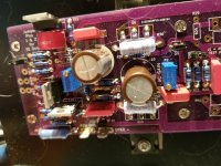
2. When measuring P1, 2, and 3 for installation, used the middle pin and the pin under the adjustment screw to dial in the correct ohm values. Don't know the terminology here and want to make sure this is the correct two before starting up -- that means that the third P lead, on the other side from the adjustment screw, is not measured.
Thanks, guys. The build is coming along well and first completion will be later today or tomorrow.
1. The Antek Transformer has an extra, purple wire coming off of it and it appears to connect to the middle windings as shown here:
https://www.antekinc.com/content/AS-2218.pdfIs this a center tap and should it be connected to the center tap connection on the mono PCB?
2. When measuring P1, 2, and 3 for installation, used the middle pin and the pin under the adjustment screw to dial in the correct ohm values. Don't know the terminology here and want to make sure this is the correct two before starting up -- that means that the third P lead, on the other side from the adjustment screw, is not measured.
Thanks, guys. The build is coming along well and first completion will be later today or tomorrow.
#1 - see build guide "Wiring" section, or search for the word "purple"Am assembling all of the stuff and have two questions:
1. The Antek Transformer has an extra, purple wire coming off of it and it appears to connect to the middle windings as shown here:
https://www.antekinc.com/content/AS-2218.pdfIs this a center tap and should it be connected to the center tap connection on the mono PCB?
2. When measuring P1, 2, and 3 for installation, used the middle pin and the pin under the adjustment screw to dial in the correct ohm values. Don't know the terminology here and want to make sure this is the correct two before starting up -- that means that the third P lead, on the other side from the adjustment screw, is not measured.
Thanks, guys. The build is coming along well and first completion will be later today or tomorrow.
#2 - see post #62 in thread. let me know if that answers that one.
Thanks, Randy. The purple goes to the chassis ground on the PSU PCB where it will join with the earth ground off of the power line. The R2 as you so carefully describe, has been measured from the center pin to the pin underneath the adjustment screw -- as shown on your fine PCB with the white dot.
All coming together and the chassis provides a certain challenge. Getting the baseplate in harmony with the bottom plate and all aligned for the screws is fiddly work. Cannot figure out how to affix the round plastic legs and am going to punt here and replace them with spring supports.
All coming together and the chassis provides a certain challenge. Getting the baseplate in harmony with the bottom plate and all aligned for the screws is fiddly work. Cannot figure out how to affix the round plastic legs and am going to punt here and replace them with spring supports.
Thanks, Randy. The purple goes to the chassis ground on the PSU PCB where it will join with the earth ground off of the power line. The R2 as you so carefully describe, has been measured from the center pin to the pin underneath the adjustment screw -- as shown on your fine PCB with the white dot.
All coming together and the chassis provides a certain challenge. Getting the baseplate in harmony with the bottom plate and all aligned for the screws is fiddly work. Cannot figure out how to affix the round plastic legs and am going to punt here and replace them with spring supports.
Purple to chassis direct is also fine, no need to go to the PCB.
Center pin (wiper) to the pin on the other side of the white line/dot. You may or may not align the white dot with the screw. If you have the straight line pins it easy to swap the orientation. If you have the "triangle" style, there's only one way to put the pot into the board. Bottom line, the key measurement is between middle pin (wiper) and the pin going on the other side of the white mark.
Last edited:
Now I am confused. Ordered the Digi-Key numbers on your (fine) BoM. P1 and P2 are straight-line pins; Pin 3 is triangle. Since I didn't know how to orient or measure them, I looked on the board pic you sent of the prototype board and copied the up/down positioning of adjustment screw -- P1 is Screw Up and P2 is screw down. Measured from the center (wiper) pin to the adjustment pin, up for P1 (242R) and down for P2 (428R) to set the value.Purple to chassis direct is also fine, no need to go to the PCB.
Center pin (wiper) to the pin on the other side of the white line/dot. You may or may not align the white dot with the screw. If you have the straight line pins it easy to swap the orientation. If you have the "triangle" style, there's only one way to put the pot into the board. Bottom line, the key measurement is between middle pin (wiper) and the pin going on the other side of the white mark.
Is this correct? There's both measuring and placement decisions and if you do not know how 3-pin trimpots are constructed, you don't know how to proceed.
Thanks.
Attachments
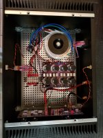
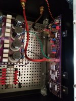
Have gotten one of the monos ready for testing and thought I would show the progress.
This is the second try at organizing the innards. Decided to push all of the power stuff as far to the left as possible to leave room for testing the circuit board with a small screwdriver -- and avoiding the PSU caps. Nothing too unusual here with an Antek 200VA transformer hooked up to the two rectifiers and passing the DC to the PSU for levelling.
The incoming power switch has a fuse and there are two CL60s feeding the transformer. The PSU also has a CL60 so there should be plenty of surge protection. We'll see.
Used 8awg speaker cable for the connection between the board and the speaker terminals -- this is the AWG used throughout the entire system and all fittings (period!) are copper. So the signal is maintained from the board to the speaker at the 8awg copper level.
This unit is ready for testing but am going to finish the second mono first, then take some deep breathes and do more reading. Have lots of testing equipment that is used for my tape decks and am ready to go at it -- once I get the nerve up, right? That first turn-on is always uncertain...
And the FrontPlate benefits from the label that Randy supplied. Will be able to see this across the room along with the bright red LED.
Attachments


That will be step one after the second box is done. Will remove the connections to the board and make sure the +/- is close enough to 24 dc -- and no other problems. Have built this design before and hope that the previous successes are duplicated.
BTW, building one of these from scratch when you are making build design decisions is a good amount of work. Don't think anyone is going to be building this Aleph in a morning, say.
BTW, building one of these from scratch when you are making build design decisions is a good amount of work. Don't think anyone is going to be building this Aleph in a morning, say.
Craig, how can you not try on a test speaker!?!? Did you fire up the power supply before wiring up the amp board?
randy: In the past have just removed the 3 board connections and hooked the +/ground and -/ground to a multimeter. Works well enough to let you know the VDC level.
Use test speakers once the PSU is OK but am thinking with all of the tests prescribed by your manual that it might be better to just do those before any connection is made. Does the board have to be under load (ala a tube amp)? My M2x seems to be fine with no load when I do the testing.
Use test speakers once the PSU is OK but am thinking with all of the tests prescribed by your manual that it might be better to just do those before any connection is made. Does the board have to be under load (ala a tube amp)? My M2x seems to be fine with no load when I do the testing.
Good news all around!
Had to visit the dentist this morning and so got off to a late start. Was able to complete the builds for both chassis, test the power supplies, and connect the boards to make sure they are not smoking -- and they are not, thankfully. Still am waiting to get the speakers hooked up as my regular test speakers are at the summer home.
VDC was right at +/-24.63 for box A and +/-24.54 for box B. Seemed very steady and lasted WAY after the power was turned off -- a bleeding resistor would be of some help here to calm those caps down. Perhaps that is part of the Soft Start PCB.
Each box is 28 pounds so this is 56 pounds of Aleph J -- when you say "a heavy amp" you are getting it right on several levels. The Front Plate Handles are wending their way from Italy and will take some time. They are good to include in your order as the 4U heatsink chassis is very uncomfortable to move about by hand.
Will be connecting them to some speaker tomorrow and starting to do the research on the adjustment procedures. The chassis legs were drilled/installed and the spring supports arrived from Amazon -- not sure whether these have any audible value for a heavy amp or not. Need to construct a bi-level stand so they and the tube 300Bs can share the same vertical space. This will be the fifth amp in my stable and space starts becoming an issue...
Will be providing several posts about the chassis, value, and musical results in the next week.
But for now all the news is good and you always love a build that causes no problems when the electricity is applied.
@Craigl59
There are bleeder resistors (R9 and R10, 2.2K) already on the PSU boards you built. If you tested them without having them connected to the main Aleph 30 board (or a board not fully optimised), then the voltage rails will take a long time to drop to near zero volts since they were not connected to a fully biased large current drawing load (~2A). So softstart PCB’s have nothing to do with that ;-)
Once you get the main PCB fully biased and dc offset comfortably under 50mV you will be good and the voltage rails should drop to near zero volts rather quickly.
This is technically an Aleph 30, not an Aleph J. The main difference is that the input differential stage is composed of JFETS in the Aleph J and not MOSFETS as it is in the Aleph 3, and Aleph 30.
To move my 5U and 4U Modushop chassis (even though some are fitted with rack handles) I always use a set of beefy gloves since the heatsinks will dig into your hands. The rack handles imho aren’t as beefy as I see in some commercial designs unfortunately. They are more for a visual effect imho.
Best,
Anand
Last edited:

Good to know that you didn't release the magic smoke! You are a very patient soul if you can wait a week before hooking up speakers!Good news all around!
This will be the fifth amp in my stable and space starts becoming an issue...
Will be providing several posts about the chassis, value, and musical results in the next week.
But for now all the news is good and you always love a build that causes no problems when the electricity is applied.
Remember that the correct number of amps to have is N+1, where N is your current amp count.
Randy: Got the parts last Thursday and the build was completed the following Tuesday -- save the final calibrations. With a day off for the SuperBowl that means that the entire build design, chassis drilling/tapping, board assembly, wiring and all else took four days. Am cranking up the amps for listening this morning after the DC offset is made.
Four days for two monoblock Aleph 30s is not, I think a long time. Am not so much patient as cautious. There is lots to go wrong in a device this complicated.
Four days for two monoblock Aleph 30s is not, I think a long time. Am not so much patient as cautious. There is lots to go wrong in a device this complicated.
Folks: To set the DC Offset, do you need to short the RCA input? Think this is what is done on the M2x and cannot find any mention of the procedure in the build guide. Thanks. When I make small changes to R1 the mv offset value doesn't change. It is around 560mv right now.
Last edited:
I thought were going to wait another week to listen. 4 days start to finish is fantastic!Folks: To set the DC Offset, do you need to short the RCA input? Think this is what is done on the M2x and cannot find any mention of the procedure in the build guide. Thanks. When I make small changes to R1 the mv offset value doesn't change.
Short the inputs to measure DC Offset. No need for an 8 ohm dummy load for this on the speaker terminals. I imagine based on mosfet matching you won't be turning R1 much or at all.
- Home
- Amplifiers
- Pass Labs
- Classic Aleph Amplifier for Modern UMS Chassis Builder's Thread