Hi All
I thought I would make the circuit as shown in
https://www.diyaudio.com/community/threads/low-distortion-audio-range-oscillator.205304/post-6597460
I replaced the 2sk30a with a 2n5484 and tried the OPA2134 and NE5532.
It does produce a reasonably clean sine wave looking at the FFT, although just looking at it on the scope I doubt it would be any better than other simpler Wein circuits I have tried. Anyway, as a hobbyist I wanted to ask how I can reduce the amplitude so that I can have a look at the output on my old HP-35660a DSA ? as soon as I try a passthrough attenuator (10db, 20db etc) the wave is clipped on the positive side ? Perhaps I have something else going wrong with my circuit ?
There is alot of talk about Victors circuit which I have running in LTSpice. Where can these boards be purchased/found? Or have other made their own ?
Cheers
Richard
There is alot of talk about Victors circuit which I have running in LTSpice. Where can these boards be purchased/found? Or have other made their own ?
Cheers
Richard
See here:
https://viccc42.wixsite.com/uld-audio
Martin
I had the infamous Heath generator. Did the fancy mods form AA. Not good enough. So I bought an old HP generator. Not good. I should just pitch it. Finally, I just quit and use my laptop to feed a Focusrite Scarlett 2i2. Orders of magnitude cleaner and no thermal drift. I will say, -150 dB is pretty impressive and as it should, exceeds the distortion of my measurement limits. No schematic, and nothing on the above link to be able to order one. Guess OBE
Make up some simple voltage divider probes with a Ziener so you don't blow the A2D input. You can have a lot of fun inside a Sharpie case.
Make up some simple voltage divider probes with a Ziener so you don't blow the A2D input. You can have a lot of fun inside a Sharpie case.
Found this.
http://tolisdiy.com/2019/03/11/low-thd-oscillator-power-supply-and-pcbs-as-case-panels/
References were from 2012 and e-bay. Later on Amazon. Nothing now. Bummer. I might like to have one.
http://tolisdiy.com/2019/03/11/low-thd-oscillator-power-supply-and-pcbs-as-case-panels/
References were from 2012 and e-bay. Later on Amazon. Nothing now. Bummer. I might like to have one.
Another thought. Modern DACs are incredibly clean. Even a JSD Atom is in the .0004 range. My new Topping in the .0001 range if given a sufficiently calculated input. The Gustard in the .00007 range. It takes a lot of bucks to measure that. Then you may need a Cordell distortion amplifier to be able to measure it. The Gen III Focusrite is a lot cleaner than my Gen II. We are talking at a level where the selection of resistors matters.
Thanks
Is the email on that page the only way to order one ?
https://www.diyaudio.com/community/threads/low-distortion-audio-range-oscillator.205304/post-4936228
Powered by 4x 9V alkaline batteries.
Enough for daily use unless you ar emeasuring 8 hours a day.
In the meantime, I have changed the balanced output according to Viktor's published schematics.
And his latest oscillators are even lower distortion than before.
Truely amazing work. Worth every cent he asks for.
Patrick
You can try to send him PM - member Vicnic:Thanks
Is the email on that page the only way to order one ?
https://www.diyaudio.com/community/...range-oscillator.205304/page-471#post-6602555
Martin
Not necessarily.It takes a lot of bucks to measure that. Then you may need a Cordell distortion amplifier to be able to measure it.
With a notch filter and an LNA, e.g. the one by Scott Wurcer:
https://www.diyaudio.com/community/...w-noise-measurement-amp-for-ikoflexer.175044/you're quickly at the harmonic level of -140dBc at a cost of less than 100 US $.
Cordell's "Distortion magnifier" was designed for measuring the THD of amplifiers and can not be used for oscillators.
I have built several low distortion oscillators 1kHz for professional use in a hifi studio in germany. All of them are better than Victors when I look at the FFT Plots in this forum. I am missing an output Attentuator and a level control Pot in Victors design. How can I adjust a defined Output level ?
How did you measure that?I have built several low distortion oscillators 1kHz for professional use in a hifi studio in germany. All of them are better than Victors when I look at the FFT Plots in this forum. I am missing an output Attentuator and a level control Pot in Victors design. How can I adjust a defined Output level ?
Victor's oscillator is normally delivered with an output voltage control.I have built several low distortion oscillators 1kHz for professional use in a hifi studio in germany. All of them are better than Victors when I look at the FFT Plots in this forum. I am missing an output Attentuator and a level control Pot in Victors design. How can I adjust a defined Output level ?
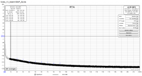
I'm attaching a THD measurement of my example of the Victor's at an output level ov 1Vrms. The signal was passed through a notch filter and the residuum was subsequently amplified by a 60dB LNA.
Assuming that the 2nd harmonic is within the noise floor at -106.7dBc (as displayed by REW), and correcting for the 10dB attenuation of my notch filter at 2kHz, the 2nd is apparently at about -156dBc.
Similar values are customarily reported in this forum.
Regards,
Braca
Attachments
Should be -9.1 dB ;-).., and correcting for the 10dB attenuation of my notch filter at 2kHz,
Regards,
Braca
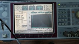
The output of the oscillator goes in a passsive twin T notch filter. There is no active buffer between Oscillator Out and notch In. All capacitors in the notch are Wima FKP2 or Vishay Roederstein MKP 1837. All resistors are precision typs 0.1% with less than 25ppm TK . The output of the notch filter was amplified by factor 51 (+34dB). The FFT was made by a R&S UPL Audio Analyzer.
Your best bet is to use a passive resistor attenuator to set the output level. A potentiometer will likely have more distortion than a quality oscillator, so you really can't use one. Similarly, you will want to avoid a buffer amplifier, so this attenuator could be built into the remote end connector of the cable to the device you're driving. To get a range of attenuations, you could build several attenuator cables with different attenuation networks. Or, if you can mechanically fit it all in, you could use a high quality switch to provide several attenuation values with the same cable and network.I have built several low distortion oscillators 1kHz for professional use in a hifi studio in germany. All of them are better than Victors when I look at the FFT Plots in this forum. I am missing an output Attentuator and a level control Pot in Victors design. How can I adjust a defined Output level ?
First I ask for your forgiveness for my bad English. I live in Germany. You're right. My Oscillators have all passive resistore attenuators in 10 dB steps at the output. The Pot for seeting the output level is conductive plastic and is located between the output buffer of the Oszillator and the Output Amplifier which drives the output resistor attentuator. I have made a lot of measurments to verify that the THD contribution of this conductive plastic Pot is negligible.Your best bet is to use a passive resistor attenuator to set the output level. A potentiometer will likely have more distortion than a quality oscillator, so you really can't use one. Similarly, you will want to avoid a buffer amplifier, so this attenuator could be built into the remote end connector of the cable to the device you're driving. To get a range of attenuations, you could build several attenuator cables with different attenuation networks. Or, if you can mechanically fit it all in, you could use a high quality switch to provide several attenuation values with the same cable and network.
The measurement setup can be seen in the picture on the left. The device with the blue LED is the 1kHz oscillator. To the left of it the passiv twin T notch Filter (green LED). On the ground the R&S UPL Audio Analyzer. The Output of the oscillator is 2.5V RMS. The transfer function of the notch at 2 kHz is 0.3511 (--9.091dB). The gain of the post notch amplifier is 51 (34.151 dB). When you look at the FFT Output of the UPL you see the Fundamental at 1.00146 kHz with a level of 0.1591 V. The notch attentation of the Fundamental is about -58dB and with 34 dB amplification the result is 0.1591 V. The y-axis ist scaled in uV. At 2 kHz you can see a very small peak at about 2.5uV. To calculate the real level of the 2. Harmonic of the oscillator you must do the following calculation : 2.5uV/(0.3511*51) = 139.662 nV. The THD of the Oscillator is then : 20*log(139.662nV/2.5V) = -145.06 dB.
Attachments

Do you need fully tuneable frequency? If yes, I would go for a state variable oscillator, as Bob Cordell in his THD-Analyzer did. I am missing a frequency range dependent filtering of the measured amplitude as Bob Cordell does is with S1 Section I and G. This might lead to an unstable amplitude regulation.I am looking to add a low distortion audio sig gen to my bench. I have been watching eBay for good deals. Any worth bidding soon rise above my budget.
Anyway, I starting looking into a DIY Signal Generator. My research turned this up. Low-distortion Audio-range Oscillator
Anyone ever build this? Sounds good but is it? There is no build tips or PCB layout. Just a diagram and parts list.
This author has a book of all his circuit designs but comes at a steep price. However, my local library has a copy and I will pick it up sometime this week.
Since the filtering you mention is in the analyzer section, the source oscillator stability will not be affected. The 3-dB point of the filtering of the residual in the analyzer section was 10X the source frequency, so that all of the harmonics through the 10, including with a 20 kHz fundamental, would be captured. This increases the noise floor a little bit for 20 kHz measurements as compared to commercial analyzers that typically LPF at 80 kHz and capture only the 2nd and 3rd harmonics of 20 kHz.Do you need fully tuneable frequency? If yes, I would go for a state variable oscillator, as Bob Cordell in his THD-Analyzer did. I am missing a frequency range dependent filtering of the measured amplitude as Bob Cordell does is with S1 Section I and G. This might lead to an unstable amplitude regulation.
IIRC, Victor gets continuous oscillator amplitude adjustment with a pot not in the signal path by changing the oscillator agc setting.
Cheers,
Bob
- Home
- Design & Build
- Equipment & Tools
- Low-distortion Audio-range Oscillator