Is this with loop cable without notch filter?It is possible to get reasonable results without AP or low-distortion oscillators. DAC is AK4490 and ADC is AK5394.
Yes. No gimmicks (e.g. thd compensation) used. ADC and DAC are synchronized through my STM32F7 USBI2S bridge.Is this with loop cable without notch filter?
< -130dBc H2 and higher harmonics even lower look to good too be true for an AK4490 @ -10dBFS generator level (?).It is possible to get reasonable results without AP or low-distortion oscillators. DAC is AK4490 and ADC is AK5394.
Care to give some details, what's your secret? Are the result consistent when using a notch filter? Any checks on an AP or similar?
Yes, I agree my measurement seems too good. However I have built 2 of these AK4490 DACs and both measure about the same on both channels. I do not have access to AP but on another thread I have posted measurements of my ES9038Q2M DAC. The measurement setup was the same. Those results look fairly ordinary to me so I do not believe the measurement setup produces overly optimistic results. The random artefacts on those graphs are most probably caused by running DAC and ADC asynchronously. I have also made measurements of the AK4490 DAC using other ADCs. In all cases H5 and above were buried in the noise floor. H2-H4 were a bit higher. So it is possible that I have hit some sweetspot or some harmonic cancellation takes place. But it does not matter much to me as these DACs were meant as "listening DACs" (as Markw4 puts it) since AK4490 does not perform properly above 192kHz.< -130dBc H2 and higher harmonics even lower look to good too be true for an AK4490 @ -10dBFS generator level (?).
Care to give some details, what's your secret? Are the result consistent when using a notch filter? Any checks on an AP or similar?
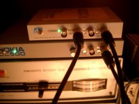
Regarding the DAC implementation my main focus has been on power supplies and output stage. Analog supplies have LT3042 regulators (separate for L and R). The power supply for DAC and ADC is a low-noise switching supply powered from a battery (5V power bank to be precise). If you think low-noise switching supply is an oxymoron here is the measured noise of the +15V opamp rail.
So the total noise from 10Hz to 90kHz is about 700nV. The 50Hz spike is due to measurement setup.
The output stage is also a bit unconventional. The first stage is single-ended with separate SE-to-balanced stage. This is the reason for the single-ended harmonic profile. I have tried more conventional balanced output stages with OPA1612 but these had higher THD. The opamps in the output stage are LM4562 as these produced the lowest THD. OPA1656 was about the same but OPA1612 was much worse (apparently I do not know how to use that). Resistors are MELFs and capacitors C0G or X7R. The large Vref capacitors are low-ESR polymers.
One more thing to mention is the USBI2S bridge (presented here). This makes it possible to run ADC and DAC synchronously which improves FFT accuracy and removes unwanted artefacts. So DAC gets the MCK, BCK and LRCK directly from ADC and USBI2S bridge synchronizes the DAC serial data to the ADC bit clock.
If you can do a synchronous averaging of FFTs, the noise will get reduced as you average more FFTs. The APx can do this, and just to put some numbers on it, with a 192kHz sample rate, 256K sample FFT, and 128 averages, the 'noise per bin' of such an FFT will be about 60dB below the broadband noise level. The combination of the wide FFT and the deep synchronous averaging grinds away a lot of noise. Practically, with an input having a -105dBV noise floor, each bin will have a noise level of around -165dBV, which should allow the residual distortion of even the APx 555 generator to be easily visible despite the noise floor.The harmonics are below the noise. The bastards are hiding. ;-)
While it's easy to select synchronous averaging on the APx, there's no reason why this can't be done with any sort of hardware. The APx does this by triggering the FFT start on the generator's zero crossings, but another way to accomplish this is to arrange for the analyzer's generator to be synchronous with the converter that is digitizing the analyzer residual. This is one of the great benefits of a generator with a sync input. Having a generator that is truly synchronous to the ADC that samples the residual, you get maximum "crud removal" and also prevent the distortion spurs from wandering among FFT bins, which only gets worse as the number of averages gets higher.
Thanks for the detailed info.Yes, I agree my measurement seems too good. However I have built 2 of these AK4490 DACs and both measure about the same on both channels. I do not have access to AP but on another thread I have posted measurements of my ES9038Q2M DAC. The measurement setup was the same. Those results look fairly ordinary to me so I do not believe the measurement setup produces overly optimistic results. The random artefacts on those graphs are most probably caused by running DAC and ADC asynchronously. I have also made measurements of the AK4490 DAC using other ADCs. In all cases H5 and above were buried in the noise floor. H2-H4 were a bit higher. So it is possible that I have hit some sweetspot or some harmonic cancellation takes place. But it does not matter much to me as these DACs were meant as "listening DACs" (as Markw4 puts it) since AK4490 does not perform properly above 192kHz.
Regarding the DAC implementation my main focus has been on power supplies and output stage. Analog supplies have LT3042 regulators (separate for L and R). The power supply for DAC and ADC is a low-noise switching supply powered from a battery (5V power bank to be precise). If you think low-noise switching supply is an oxymoron here is the measured noise of the +15V opamp rail.
View attachment 1014274
So the total noise from 10Hz to 90kHz is about 700nV. The 50Hz spike is due to measurement setup.
The output stage is also a bit unconventional. The first stage is single-ended with separate SE-to-balanced stage. This is the reason for the single-ended harmonic profile. I have tried more conventional balanced output stages with OPA1612 but these had higher THD. The opamps in the output stage are LM4562 as these produced the lowest THD. OPA1656 was about the same but OPA1612 was much worse (apparently I do not know how to use that). Resistors are MELFs and capacitors C0G or X7R. The large Vref capacitors are low-ESR polymers.
One more thing to mention is the USBI2S bridge (presented here). This makes it possible to run ADC and DAC synchronously which improves FFT accuracy and removes unwanted artefacts. So DAC gets the MCK, BCK and LRCK directly from ADC and USBI2S bridge synchronizes the DAC serial data to the ADC bit clock.
In my limited experimentation with 4490/4430, butchering around in my RME's as those chips are not avaible atm for own designs, I've found they are very sensitive on the Vref pins and Vcom pin, wrt to any tendency for tank circuits here. They draw ripple current at MCLK/2 and when that hits an anti-resonance of paralleled bypass caps or other reasons why the impedance isn't really low at RF the HD goes up quickly. I've always measured directly at the chip's output and even in the best case I never managed better than -120dBc at any levels above -30dBFS. With significat variation from part to part (from that limited set of two chips of one kind).
When looking at the signal after the filter stage (RME implemented balanced MFB topology in a superbal config, using OPA1602's) I always saw various amounts of cancelling. I've also experimented with applying digital DC bias and summing of channels (up to four), together with slightly pulling/pushing the Vcom and sometimes I could achieve breathtaking low HD levels a certain sweet spots of level and frequency... not a very practical solution, such a one-trick pony...
I agree with @IVX that heavy lowpass-filtering at or sligtly below the test frequency is far more efficient and convenient to reduce the harmonics at any level, and it has a noise benefit as well.
Don't know anything about horses but in my case the sweet spot seems to be a rather big spot.sometimes I could achieve breathtaking low HD levels a certain sweet spots of level and frequency... not a very practical solution, such a one-trick pony...
Attachments
^ Impressive.
A stiff (milliohms) and well damped Vref from many MHz down to DC definitely helps the 4490/4493 HD at higher levels as the Vref current draw is signal-dependent. I have designed a Vref update (LT3042-based) for my RME's (all DAC and ADC channels sharing one single Vref) but haven't found the time to finalize the build and install it... I'm hoping to get HD improvements but the main purpose is a) to reduce Vref 1/f noise and drifts and more importantly b) having them in sync on DAC and ADC sections for some specialized measurement purposes (and it might sound better as well, if only for expectation bias, haha ;-)
A stiff (milliohms) and well damped Vref from many MHz down to DC definitely helps the 4490/4493 HD at higher levels as the Vref current draw is signal-dependent. I have designed a Vref update (LT3042-based) for my RME's (all DAC and ADC channels sharing one single Vref) but haven't found the time to finalize the build and install it... I'm hoping to get HD improvements but the main purpose is a) to reduce Vref 1/f noise and drifts and more importantly b) having them in sync on DAC and ADC sections for some specialized measurement purposes (and it might sound better as well, if only for expectation bias, haha ;-)
I've had little luck with exploiting the sync'ed averaging features on my personal 2322 (trigger never works reliable in any of the many modes and the damn SW is unable to simply discard aquisitions that are deemed too inaccurate, rather it aborts the whole process. This makes higher averages than 16 practically impossible).If you can do a synchronous averaging of FFTs, the noise will get reduced as you average more FFTs. The APx can do this, and just to put some numbers on it, with a 192kHz sample rate, 256K sample FFT, and 128 averages, the 'noise per bin' of such an FFT will be about 60dB below the broadband noise level. The combination of the wide FFT and the deep synchronous averaging grinds away a lot of noise. Practically, with an input having a -105dBV noise floor, each bin will have a noise level of around -165dBV, which should allow the residual distortion of even the APx 555 generator to be easily visible despite the noise floor.
While it's easy to select synchronous averaging on the APx, there's no reason why this can't be done with any sort of hardware. The APx does this by triggering the FFT start on the generator's zero crossings, but another way to accomplish this is to arrange for the analyzer's generator to be synchronous with the converter that is digitizing the analyzer residual. This is one of the great benefits of a generator with a sync input. Having a generator that is truly synchronous to the ADC that samples the residual, you get maximum "crud removal" and also prevent the distortion spurs from wandering among FFT bins, which only gets worse as the number of averages gets higher.
On the APx it may actually work better.
Trigger-less synced averaging in loopback DAC/ADC setting work well for me and I'm using for many many years very successfully, to extreme level... with caution, as even in full sample sync even the tiniest clock jitter and drift etc reduces the high frequencies by often unknown amounts. Usually I'm adding a known pilot tone to check for that droop.
I still have doubts about the ADC chip (AK5394). I have a few of them and the thd seems to be quite inconsistent channel-to-channel or chip-to-chip. When I get the ES9822PROs I will need to return to these measurements.^ Impressive.
A stiff (milliohms) and well damped Vref from many MHz down to DC definitely helps the 4490/4493 HD at higher levels as the Vref current draw is signal-dependent. I have designed a Vref update (LT3042-based) for my RME's (all DAC and ADC channels sharing one single Vref) but haven't found the time to finalize the build and install it... I'm hoping to get HD improvements but the main purpose is a) to reduce Vref 1/f noise and drifts and more importantly b) having them in sync on DAC and ADC sections for some specialized measurement purposes (and it might sound better as well, if only for expectation bias, haha ;-)
Yeah, below -120dBc we have always to be conservative wrt harmonic cancelling.I still have doubts about the ADC chip (AK5394). I have a few of them and the thd seems to be quite inconsistent channel-to-channel or chip-to-chip. When I get the ES9822PROs I will need to return to these measurements.
I'm seeing it all the time when double-checking results. Sometimes I see unbelievably stellar results in plain cable looback with my RME's but it's always cancelling at work. While cancelling for even order is quite commonly understood to happen, it also can happen for odd orders.
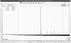
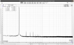
FWIW, this is the best I can get for 1kHz @ -10dBFS from the AK4490 in the RME, using the RME XLR output at +13dBu (other Ref.Levels are worse --> indicative of cancelling). I've used my AP as notch filter and makeup gain amp, with the front-end running with 15dB of headroom (to make its contribution low otherwise again risk of cancelling) and the residual then fed back to the RME's ADC.
Fully sync'd playback&recording, that is, allowing for rectangular window and block-averaging, done off-line (x100 int his case, to illustrate that point as well). The resolution increase is significant but useless in the end as the AP's frontend and notch is not likely to be better than -140dB best case. But theoretically I would be able to see stuff at -160dBc here.
The 5.5kHz needle is the -100dB (wrt to fundamental) pilot tone, for leveling etc. Plots says dBV units but it's actually dBc, of course.
Well, its nice to know that one's not alone in the world.
FWIW here is my take at an OPA1612 buffer for my 2005 Victor's.
I modified it by changing the 600R output makeout resistors to 100R and wanted to add a buffer.
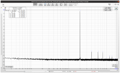
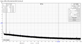
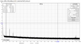
My first attachment shows the spectrum of a 2.5Vrms oscillator output passed through a notch filter and Groner's 60dB LNA. The 2nd is at -154dBc.
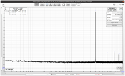
Adding the buffer (master/slave topology, noninverting input) increased the 2nd by 12dB and added a 3rd one (2nd attachment, 2x1611 means a single 1612).
FWIW here is my take at an OPA1612 buffer for my 2005 Victor's.
I modified it by changing the 600R output makeout resistors to 100R and wanted to add a buffer.
My first attachment shows the spectrum of a 2.5Vrms oscillator output passed through a notch filter and Groner's 60dB LNA. The 2nd is at -154dBc.
Adding the buffer (master/slave topology, noninverting input) increased the 2nd by 12dB and added a 3rd one (2nd attachment, 2x1611 means a single 1612).
Attachments
Hi,
How do you set a specific output voltage value for this oscillator? For example if you want to test a preamplifier with 1V or 1.25V . An oscillator with which I cannot set a defined output voltage of e.g. 50mV to 3V would have no practical use for me, except that it produces nice sinusoidal oscillations. The OPA 1612 is a difficult to handle OPAMP. Compared to the LM4562, it produces more noise and higher distortion when used as an oscillator IC or as a post notch amp. It works very well in the non-inverting mode with voltage around 3V RMS max as a buffer.
How do you set a specific output voltage value for this oscillator? For example if you want to test a preamplifier with 1V or 1.25V . An oscillator with which I cannot set a defined output voltage of e.g. 50mV to 3V would have no practical use for me, except that it produces nice sinusoidal oscillations. The OPA 1612 is a difficult to handle OPAMP. Compared to the LM4562, it produces more noise and higher distortion when used as an oscillator IC or as a post notch amp. It works very well in the non-inverting mode with voltage around 3V RMS max as a buffer.
Hi,
Here's a link to Victor's oscillator. As you'll observe, output level is controlled by a pot adjusting AGC level over a limited range. You'd have to add external attenuation if you need amplitude lower than what's offered by the pot's control range.
https://www.diyaudio.com/community/...range-oscillator.205304/page-471#post-6602555
This link should take you post 9407 in this thread. I'm still clumsy in the new platform.
Works and hits the target, the latest schematic from Viktors.This link should take you post 9407 in this thread. I'm still clumsy in the new platform.
It easily has a more than 10dB adjustment range via AGC and the rest you do with 10dB-stepped attenuators. Noise-wise (control-loop contribution) the Osc works best at higher amplitudes.Hi,
How do you set a specific output voltage value for this oscillator? For example if you want to test a preamplifier with 1V or 1.25V . An oscillator with which I cannot set a defined output voltage of e.g. 50mV to 3V would have no practical use for me, except that it produces nice sinusoidal oscillations. The OPA 1612 is a difficult to handle OPAMP. Compared to the LM4562, it produces more noise and higher distortion when used as an oscillator IC or as a post notch amp. It works very well in the non-inverting mode with voltage around 3V RMS max as a buffer.
As for OPA1611/OPA211 vs LM4562/LME79720, many a designer would beg to differ. The LM is king of uncontrolled popcorn noise and also king of RF demodulation, both of which has cost a company I've worked for many $ and a lot of headaches.
The oscillators if have built are using a bridged T filter network and a FET which acts as a variable resistor. In this topology the OPA 1612 was worst because of its low input impedance. In order to achieve ultra low distortion and ultra low noise design, the resistances in the frequency-determining network must be made as small as possible. In my experience, LM4562 and OPA 1656 work best in this topology. But I already have some LM 4562 which had too much noise. However, in order to be able to use the oscillator signal, it must be decoupled from the oscillator IC with a buffer, because every further load change, e.g. due to the test object, has an effect on the oscillator itself.
I'm not questioning your experience here but input impedance (DM) difference is negligible (as per datasheets): 30k for 4562 and 20k for 1612.
Fully agree on the loading, though ususal loads like (pre)amp inputs are benign.
And I like your use of bridge-T for the bandpass core (asuming you use an inverting OpAmp bandpass), I also find that superior to the simple R/2+2C + R//C bandpass as it has higher Q at the same gain (and it has the same noise gain, so no penalty here), and the higher the gain the higher the Q whereas for the simple bandpass the Q is fixed and low. Equal capacitor values are another bonus.
For injection-locking a lower Q might be a better choice, though (gut feeling as of yet).
Speaking of which, this evening I was about to try it with the Viktors but for the life of my I can't find the oscillator in my lab, misplaced it somewhere... damn it...
Last edited:
- Home
- Design & Build
- Equipment & Tools
- Low-distortion Audio-range Oscillator