Has S Groner updated his work on opamps recently?
I would be interested in an opamp test fixture. Maybe create one if there isn't already something.
I would be interested in an opamp test fixture. Maybe create one if there isn't already something.
Hi Demian,
I know I have seen op amp test jigs from Linear Technology and TI in the app notes. They were never too complicated. Looking for any aspect in particular?
I suspect a few simple setups for noise and slew rate / distortion / DC offset could be wired up on one PCB. The real challenge is the shielding for the high performance op amps, then you have single and dual (+ quad if you want) versions. A die cast box for the circuit with another thinner one for a lid might work well.
The mechanical realization will be the PITA on these. Maybe one case with interchangeable test PCBs? An external, low noise power supply that plugs in as well.
-Chris
Applications of low distortion sine wave oscillators are mostly for THD-checking on pre-/power-amplifiers but sometimes such oscillators are also to find in motor control units for synchronous motors in record player/turntables - go for an example to post #16 under
Homebrew Motor Control Linn LP12 - Circuit Description wanted for Sine Wave Osc.
This oscillator based on a SVF.
But maybe this sine wave oscillator topologies provide even better results.
http://www.users.on.net/~endsodds/aocct.jpg
Low-distortion Audio-range Oscillator - RED - Page82
check out also
Linn Lingo vs. Dr. Fuß or Square-Wave vs. Sine Wave Oscillator for Motor Control
Hi Demian,
What parameters did you want to focus on? I suspect you would have more than one jig. Double when you consider single and dual op amps. The quads should be pretty similar to the dual ones.
All that points to maybe a modular design where you can plug in whatever board you need so you aren't messing around with connectors and power supplies. Just one common test connector array and power supply with shielded case to minimize the amount of building you need to do. Less mistakes too when all you need to do is connect once, then just change test boards.
-Chris
I was really looking for a fixture for testing for various distortion parameters similar to Groner's. Just too lazy to lay one out. JLBPCB's prices are so reasonable the cost is not an issue. Theat fixture would be very specific and not easily useable for other testing.
I have a Quantech that can test for noise but not for distortion, or any of the myriad other parameters that are important for quantifying parts. However it has been really useful for spotting fakes.
I have a Quantech that can test for noise but not for distortion, or any of the myriad other parameters that are important for quantifying parts. However it has been really useful for spotting fakes.
Sensitive to good or bad vibes 🙂 ?I have seen 1 KHz crystals, and I might even have one. They are huge! Very vibration sensitive.
Hi Demian,
Can you provide a link to the fixture you are thinking of?
Also, I found some vibration damping grommets and shoulder washers in case you are interested. I ordered a bunch that are due in about a month. They have a 3mm center hole. I tried to deal with Sorbothane, but they were not only very expensive, they blew me off. That forced me to China where I found what I needed much more easily.
Hi dreamth,
Any, but picks up on bad vibes from quite a distance away!
RE Distortion fixture: Look at page 8 of this great work: https://www.nanovolt.ch/resources/ic_opamps/pdf/opamp_distortion.pdf and I think there are more pictures of his setup further. I think it also tests CM distortion and input cap modulation distortion.
I was really looking for a fixture for testing for various distortion parameters similar to Groner's. Just too lazy to lay one out. JLBPCB's prices are so reasonable the cost is not an issue. Theat fixture would be very specific and not easily useable for other testing.
I have a Quantech that can test for noise but not for distortion, or any of the myriad other parameters that are important for quantifying parts. However it has been really useful for spotting fakes.
hey Demian.... are you retired yet? I have an interesting test and results I am going to e-mail attachment to you. Prepub. Comments/questions welcomed.
I sold everything except the test equipment and now live 100% full time along with 40,000 other Americans in Bangkok. Just doing R&D and audio for hobby.
Hope you are in good health and stay safe.
Enjoy,
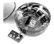
Victor's oscillator in a box
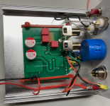
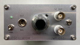
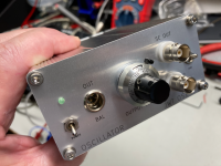
I decided to build a slightly more professional-looking enclosure for Victor's oscillator. Better shielding and improved connectors were the main goals. Similar to my stepped attenuator, I put it into a small 50x100x100 mm aluminum case. I designed the panel in KiCad and had it fabbed in aluminum by JLCPCB.
I replaced the level control with a 10-turn pot and vernier dial. The RCA jacks were replaced with BNC connectors. I made provisions for a future differential output, probably consisting of an OPA1656 on a small piece of perf board (I don't have anything to test yet that has differential inputs).
Power comes from an external battery box with 4x 9Volt batteries.
Cheers
Attachments
Nice work ! If you want the shielding to be effective, get rid of the insulated BNC connectors.
Thanks - I thought about that but decided to go with insulated jacks and have a chassis ground lift switch which optionally grounds the shields to the chassis.
In a complete instrumentation setup, I can ground the boxes externally in a star configuration which would avoid loops caused by the shielded cabling. That is why balanced operation would be ideal.
Of course, the whole mess could be in a Faraday cage. 😀
In a complete instrumentation setup, I can ground the boxes externally in a star configuration which would avoid loops caused by the shielded cabling. That is why balanced operation would be ideal.
Of course, the whole mess could be in a Faraday cage. 😀
Nice work ! If you want the shielding to be effective, get rid of the insulated BNC connectors.
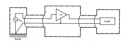
You have to make provision for the shielding to be earth-grounded. Illustrated in Morrison (Grounding and Shielding Techniques for Instrumentation) :
Attachments
wtnh: What is origin of your 10-turn potentiometer? I used inexpensive chinese clones of blue Bourns in older builds of my distortion calibration adapter and about every second piece introduced H2 and/or H3 distortions at levels seriously above expected performance of the Victors oscillator. You would do not want that in your nice instrument.
Yes - the pot is one of those suspects. It does say Bourns - Mexico. It is wire-wound. Surprisingly, it is very smooth with no noticeable dropouts from end to end.
I would not use one of these in a signal-passing analog circuit. In the case of Victor's oscillator, it is used only to set a DC voltage in the AGC circuit - see his recent schematic in this post.
I would not use one of these in a signal-passing analog circuit. In the case of Victor's oscillator, it is used only to set a DC voltage in the AGC circuit - see his recent schematic in this post.
Hello Victor,
did you measure the new generators?
did you measure the new generators?
New revision of the oscillator board has been made. Now the AGC fet is connected to the non inverted input of the opamp. This configuration is less sensitive to interference, less parasitic capacitance at the inverted input of the opamp and also the signal over the fet can be two times lower due to the non inverted gain of the opamp.
Vic.
- Home
- Design & Build
- Equipment & Tools
- Low-distortion Audio-range Oscillator