I used 50 ohm trimmers, however, I changed R6 from 33 to 47 ohms, only because that was what I had in stock closest to 33 ohms.
I purchased 2 more H2V2 kits from the DIYStore to attempt to build a balanced version at unity gain to use inline with my balanced BA2018 preamp.
I decided to check my work on the single stereo board version before attempting to adjust a board wired for balanced operation.
I made an error yesterday with my adjustments, I had set the 1K sine wave generator so that I had 0.5 VAC into a 10K ohm load BEFORE making any T2 adjustments. What I found today is that when adjusting T2, the output voltage will change also. So I had to adjust T2, then change the sine wave generator to 0.5 VAC and then T2 again.
My T2 values today are much different from yesterday when I did not make the necessary output voltage adjustments.
Revised T2 values for 1% H2 are (with 0.5 VAC output into a 10K load):
L = 10.60 VDC
R = 10.47 VDC
I've been listening to it inline from my Balanced Zen Line Stage (RCA outputs) to my ACA v1.6 with mods by Tungston Audio. Even in my workshop with questionable acoustics, the room is much fuller than without it. Now to pack it up and ship it to my friend.
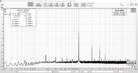
Here are pictures of the "Left" channel H2V2 PCB wired with an XLR connector with one side to Pin 2 and the other side to Pin 3 with Pin 1 to ground. Adjustment was easy, it did take some time to get the T2 values on each side of the board to achieve the lowest H3 value.
T2 values (0.5 VAC output into 10K ohm load):
L+ = 10.57 VDC
L- = 10.25 VDC
The single stereo board measured 0.30 & 0.31% H3 with 1% H2, with the balanced board the best I could get was 0.39% H3 at 1% H2.
T2 values (0.5 VAC output into 10K ohm load):
L+ = 10.57 VDC
L- = 10.25 VDC
The single stereo board measured 0.30 & 0.31% H3 with 1% H2, with the balanced board the best I could get was 0.39% H3 at 1% H2.
Attachments
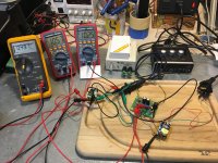
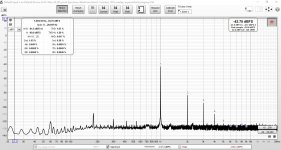
Here is the Right channel, wired the same as the left channel.
T2 values (0.5 VAC output into a 10K ohm load):
Right + = 10.61 VDC
Right - = 10.27 VDC
This channel I was able to reduce H3 to 0.28% with 1% H2.
The "left" kit JFETs bag was marked 10.3 & the "right" kit was marked 10.5. I wrote this number on each PCB with a Sharpie.
T2 values (0.5 VAC output into a 10K ohm load):
Right + = 10.61 VDC
Right - = 10.27 VDC
This channel I was able to reduce H3 to 0.28% with 1% H2.
The "left" kit JFETs bag was marked 10.3 & the "right" kit was marked 10.5. I wrote this number on each PCB with a Sharpie.
Attachments

@EU,
one set from Nelson ist still left.
But please no UK guys because the Brexit changes so much (paperwork, custom declaration, ...) we tried twice times a padded envelop and all came back to me. The cheapest shipping costs is now a small parcel for 8€! 😡
one set from Nelson ist still left.
But please no UK guys because the Brexit changes so much (paperwork, custom declaration, ...) we tried twice times a padded envelop and all came back to me. The cheapest shipping costs is now a small parcel for 8€! 😡
I chose Vp at 2.50 to 2.59 volts, which Idss corresponds to about 28 mA.

Hi PaPa. I am tried to build H2 V2 with general purpose PCB.🙂
I bought totally 40 J113 with 2 sources and cannot find anyone fit the criteria (Vp 2.5 to 2.59V and Idss 28mA), as they:
1. Vp all under 2.25V and 80% under 2.00V
2. For Vp=2.18GV, Idss is about 24mA
Any suggestion for adjusting the values for R6 and P1 to those J113 with Vp around 2.00V to 2.2V? Thanks!
I feel your pain Carsten....😉
Pete
Pete
@EU,
one set from Nelson ist still left.
But please no UK guys because the Brexit changes so much (paperwork, custom declaration, ...) we tried twice times a padded envelop and all came back to me. The cheapest shipping costs is now a small parcel for 8€! 😡
Hi PaPa. I am tried to build H2 V2 with general purpose PCB.🙂
I bought totally 40 J113 with 2 sources and cannot find anyone fit the criteria (Vp 2.5 to 2.59V and Idss 28mA), as they:
1. Vp all under 2.25V and 80% under 2.00V
2. For Vp=2.18GV, Idss is about 24mA
Any suggestion for adjusting the values for R6 and P1 to those J113 with Vp around 2.00V to 2.2V? Thanks!
Did anybody responded back to you on this query as I am also interested to learn?
Thanks
Last edited:
It has been a long bumpy ride...thank you for your perseverance Carsten and...
Yes, thank you Santa Papa You gave us wonderful toys for Christmas.
Happy Holidays to all!
Pete
Yes, thank you Santa Papa
You gave us wonderful toys for Christmas.Happy Holidays to all!
Pete
Last Board is on the way. 🙂
@Nelson, thanks again for the little toy! 🙂
Did anybody responded back to you on this query as I am also interested to learn?
Not yet.
From the OnSEMI datasheet, J113 Vp [ which is equal to -Vgs(off) ] is ranging from 0.5 to 3.0V. And most of my J113 got Vp range from 1.5 to 1.9.
I have an idea of:
1. measuring Idss of the J113
2. put the J113 to the H2 V2 board and tune the trimmer until the Ids equal to Idss
3. measure the corresponding voltage V at T2
4. tune the trimmer again to maintain voltage at T2 equal to V-0.1
5. done?
Or the best way is using the audio input of the PC to measure the distortion?😕
Did anybody responded back to you on this query as I am also interested to learn?
I will take a look at it.

Has anyone used this with a musical instrument? I'm wondering how the H2 would work with an electric guitar as a JFET boost/buffer. There's some niche fuss about the perfect clean boost for clean signals... maybe this is the mystical lost circuit.
I’ve really been enthralled with my two Pass amps this year and now with the ACP+ as well. There may be something to this negative H2 business… 😉
I have a handful of good sounding class d amps that I use throughout the house. The H2 may just be the ticket to throwing some more life in these systems, which I am very happy with, but not as engaging as my main system.
Never ending fun. 😀
Dang. Store out of stock. Ha!
I have a handful of good sounding class d amps that I use throughout the house. The H2 may just be the ticket to throwing some more life in these systems, which I am very happy with, but not as engaging as my main system.
Never ending fun. 😀
Dang. Store out of stock. Ha!
Last edited:
Wow! That was certainly a wonderful surprise! Thank you much Carsten!
Happy building all!
Pete
Happy building all!
Pete
Hi Pete,
there is a little gift on the way. 🙂
- Home
- Amplifiers
- Pass Labs
- H2 V2 BUILD