I did try a disc of glass mounted on a polymer substrate. It was the worse sounding of all the materials.
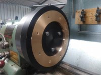
Have you tried POM, I have made 6 platters so far for SP10mk2 Stainless Steel, SS/POM, Gunmetal, Gunmetal/POM and OEM/POM. Bolting 20mm POM to the OEM platter damped ringing effectively.
The best by far is thick 40-60mm POM with a ring underneath to keep COM low and provide some rigidity to the platter. This platter also uses a de-coupled spindle, the LP spindle does not touch the motor spindle.
SP10 platter bonded Acetal - YouTube
Attachments

This platter also uses a de-coupled spindle, the LP spindle does not touch the motor spindle.
Hallelujah!
Bearing shaft to spindle machined as one piece is one of my biggest pet peeves when it comes to turntables touting as the "ultimate" or super "high end" product when the noisiest part below the platter is not decoupled from the spindle that physically touches the LP!
Hallelujah!
Bearing shaft to spindle machined as one piece is one of my biggest pet peeves when it comes to turntables touting as the "ultimate" or super "high end" product when the noisiest part below the platter is not decoupled from the spindle that physically touches the LP!
I really don't see an issue with a well designed and engineered turntable.
My DD turntable, if spun by hand to something like several hundred RPMs, and with a sensitive electret microphone capsule fastened to the machine's base, exhibits no noises.
And even placing my ear an inch or two above the fast rotating spindle, I can detect absolute silence.
So I'm quite cerain that at normal 33 1/3 RPMs it would be even more silent.
It's all in the nature of manufacturing. 😎
The following page describes an experiment in which a microphone is attached to the bottom of a spindle bearing housing, with cartridge playing.
Particularly the playable sound clip (toward the bottom of the page) makes it obvious that the breakthrough from the cartridge (conveyed through the spindle and bearing housing structure) dominates the contribution of the spindle bearing itself.
Turntable Main Bearing Vibration, Part III
Incidentally, a similar technique could be used to characterize the vibration isolation of a belt or idler mechanism; by comparing the output of a microphone bonded to the motor casing to the output of a microphone bonded to the spindle bearing housing.
FWIW, from previous experience with POMs and modified PPEs (Noryl, Lemalloy, Xyron), at least some of the PPEs were better at vibration absorption, and AFAIK have been used in the production of optical drive disc mechanisms.
Regarding metal choices, the marine (especially naval), automotive, and machine tool industries have all put considerable research into vibration-damping alloys. Dura-Bar G2, Vacrosil, Sonoston, Gentalloy, Silentalloy, Nitonol are some of the names that come immediately to mind.
Among these, Silentalloy is a type of stainless steel (3% Al, 12% Cr, Fe). OTOH, it is strongly magnetic.
kind regards, jonathan
I've been running a de-coupled spindle since I went to 20mm POM bonded to a base. 40mm thickness allows the addition of the de-coupled spindle without having to cut the OEM spindle.
I have spent a considerable amount of time designing, making and testing various upgrades to the SP10mk2. Removing the motor from the OEM chassis and mounting it in a well damped resin/bentonite plinth and the POM platter have made huge improvement on the already competent SP10.
All of the mods were intended to increase rigidity of the motor and damp vibration energy.
A list of mods
Decoupled spindle
60mm thick POM platter
Damping added to the inside of the motor housing
Motor mounting modified from 4 to 3 bolts and fixed at 3 points. So the motor mounting face does not touch all the way around
Bearing collar clamp fixes the bottom of the bearing housing rigidly to the plinth.
2500rpm? I think you added a '0'? 🙂
My Premotecs rotate at 250rpm.
Andy
Yes, it was not a good example, high speed is 10000 RPM ! 😀 !
Motor 775 de Alta velocidad ajustable DC 12/24 10000 RPM -
Last edited:
Any mechanical rotating component will exhibit noise. I found my contact mic nowhere sensitive enough to measure bearing noise. A phono cart is way more sensitive.
My method for measuring bearing noise is to place the stylus on a gauge block on the plinth monitored by a HP dynamic signal analyzer. Reference set with a 7cm/s 1kHz tone played and markers set to reference.
Spin the platter by hand and the HP picks up the bearing spinning albeit 70dB down. I know it's bearing because you can see the peak track down in F as the platter slows.
I subscribe to the Korf blog and seen that clip. It was the motivation for me to experiment with the de-coupled spindle.
My theory is, most of the energy imparted into the bearing comes via the platter as the LP/spindle interface is quite small. (I will test this one day). Some/all vibration energy traveling down the bearing will be reflected back to the LP via the platter, how much depends on the topology of the bearing/ball interface. 40mm POM has better damping properties than a metal spindle.
I have made noise floor measurements. Play a 1kHz 7cm/s tone and measure narrow band 0-200Hz, with the POM platter and de-coupled spindle noise floor dropped 3dB. This is audible
Any mechanical rotating component will exhibit noise. I found my contact mic nowhere sensitive enough to measure bearing noise. A phono cart is way more sensitive.
My method for measuring bearing noise is to place the stylus on a gauge block on the plinth monitored by a HP dynamic signal analyzer. Reference set with a 7cm/s 1kHz tone played and markers set to reference.
Spin the platter by hand and the HP picks up the bearing spinning albeit 70dB down. I know it's bearing because you can see the peak track down in F as the platter slows.
Without being obsessive, I believe that 70dB down while playing a record is more than acceptable performance, since records themselves don't have "absolute" silence, primarily due to manufacturing tolerences, vinyl quality/purity, and the fact that the stylus is contending with the friction of plowing through the groove in motion.
Besides, the musical content surely is not hindered by such a low value of any possible "noise" created by the rotation.
I don't "go nuts" over respectable performance, however I do enjoy my music, I'm just not in that "fanatic" group.
I agree wiseoldtech, I think that some people just do a deep dive into the rabbit hole and start chasing problems that don't exist. I'd be surprised if any audio nut over 50 could hear a tone at -70 in even the most ideal environment, particularly if it was above 10Khz. Because there always seems to be anything that you could wish for out there, I suppose there's a disc somewhere that has a "silent" groove on it. If you had a well engineered TT with direct or belt drive, I would put money on the surface noise of the LP being far above -70dB and the noise would also be accompanied by all the associated pops and crackles from inevitable groove contamination. Comparing any commercial turntable to a cutting lathe is also a spurious argument. Lathes were engineered to cope with the cutting forces of creating a master (particularly DMM) Naturally, the engineering was an order or two of magnitude greater than a mere HiFi turntable, the unit needed to be able to fill the role of a standard with respect to creating a master recording. Thus, the machines had enormous reservoirs of mechanical strength and over-engineered drive components.
It's worse then that, the lathes deliberately add rumble to the disks (and go to some trouble to do it!), this is a feature not a bug.....
Basically the depth of cut is varied at a sub audio rate so as to remain only as deep as is required to make the minimum depth due to vertical modulation hit a target value.
This is helpful as the approximately 90 degree included angle of the cutting stylus makes the groove width at the top surface ~ twice the depth at any point, and if you want to maintain a reasonable land you need that to be factored into the speed of the carriage and hence the length of the disk is impacted by average depth of cut.
A lot of the turntable bearing design is actually about doing well enough without needing precisely preloaded super precision angular contact ball bearings (At $500 each) running on precision ground hardened shafts (Or active magnetic bearings or whatever other expensive tosh), that sort of thing adds way too much cost for a consumer product.
Remember also that most of the classic lathes were 1970s or earlier designs, no modern magnetics, no coreless motors, (And, until the VMS80 or the retrofit motors), relatively low pole counts.
DMM is of course a whole other can of worms.

Many years ago, on tomorrow's world ( a UK TV programme ) they showed an new design of electric motor that was going to "revolutionize " tape recorders and Walkman's, it consisted of a slotted metal ring that had a piezoelectric layer underneath that caused it to flex and " walk " a ring with a similar action to a caterpillar, can anyone else remember what happened to this invention? On the right I have drawn a different design that would reduce the possibility of the " legs " taping on the revolving surface, causing vibration.
I miss programs such as tomorrow's world, QED, horizon, the secret life of.... ( with Tim Hunkin), and despair at the current drivel.
That's basically a strain wave gear with a piezo actuation layer, I can see uses for it but probably not for those applications.
A coreless BLDC direct drive is probably going to be superior in essentially all ways.
"Tomorrows world", did they EVER, even just once call it right?
A coreless BLDC direct drive is probably going to be superior in essentially all ways.
"Tomorrows world", did they EVER, even just once call it right?
I don't "go nuts" over respectable performance, however I do enjoy my music, I'm just not in that "fanatic" group.
What a buzz kill! Look, I agree with you in general on the fanaticism of audiophilia. But I happen to enjoy it as an intellectual exercise since the title of the thread literally started with the word "Ultimate" so I indulge. Is it necessary for you repeat the same argument over and over again in every thread? Is it a crime to indulge when the OP gave free rein for such exercise?
Basically the depth of cut is varied at a sub audio rate so as to remain only as deep as is required to make the minimum depth due to vertical modulation hit a target value.
This is helpful as the approximately 90 degree included angle of the cutting stylus makes the groove width at the top surface ~ twice the depth at any point, and if you want to maintain a reasonable land you need that to be factored into the speed of the carriage and hence the length of the disk is impacted by average depth of cut.
@dmills, do you have any recommendations for literature that covers the cutting depth topic in detail? I am aware that the lacquer layer is only about 0.2mm thick, therefore cutting too deep and into the aluminum substrate below would be catastrophic.
The literature that I have been able to find suggests that the depth limiting is accomplished through mono summing of LF content, and keeping the cutting stylus rake angle at 90 degrees to the groove. (I haven't been able to find any literature from the studio industry that supports Jon Risch's contention that orienting the playback stylus rake angle at 92 degrees to the groove gives the most accurate results.)
However, an article from the July 1975 issue of Studio Sound states (for mono discs) "research indicates that the chisel should cut the disc at a trailing angle of about 88º. A trailing angle of less that 90º is essential to exclude the possibility of the chisel digging into the disc surface."
For stereo discs, the same article continues "research indicates that the chisel should cut the disc at a trailing angle of about 75º."
(presumably since stereo LF content of the left channel will be out of phase with that of the right channel, causing the chisel to cut deeper).
This would make sense if a key goal was to keep the cutting chisel from digging too deeply into the 0.2mm-thick lacquer layer, but this position is not supported by the other articles that I have been able to find.
Any recommendations for reading material that could shed additional light on this issue will be highly appreciated.
* Apologies to the thread creator for veering so far off-topic.
\I agree wiseoldtech, I think that some people just do a deep dive into the rabbit hole and start chasing problems that don't exist. I'd be surprised if any audio nut over 50 could hear a tone at -70 in even the most ideal environment, particularly if it was above 10Khz.
We all have different circumstances, I'm retired and as this is a hobby I spend my time playing in the shed building and testing audio gear. I just happen to be on the TT ATM.
No one I now of can hear a tone at -70dB over background noise BUT the thing everybody neglects is the effect this has in the audio band as modulation of the signal and the compound effect.
View attachment 966484
Tomorrow's World ( a UK TV programme ) showed an new design of electric motor that was going to "revolutionize " tape recorders and Walkman's, it consisted of a slotted metal ring that had a piezoelectric layer underneath that caused it to flex and " walk " a ring with a similar action to a caterpillar.
That's an ultrasonic motor, which has found wide-scale adoption in camera lens focusing mechanisms.
SHINSEI Corporation|Technology
One of the more interesting yet pragmatic turntable motors was the linear direct drive design introduced on Sanyo-Otto's TP-L1 (subsequently used across many of the Fisher-branded mass-market turntables).
The underside of the aluminum platter integrated a smaller-diameter downward-facing ring, which carried a circular rubber magnet (precision-magnetized with 120 poles). The circular magnet was driven by three plinth-mounted coils that were arranged immediately outside the 120-pole ring magnet. Electric drive was via a three-phase motor controller.
With no slots, Sanyo-Otto's design was devoid of any mechanism that could cause torque ripple.
And since the motor structure was confined to the platter and plinth-mounted coils, and was therefore separate from the spindle and bearing, the bearing could be revised to accommodate different platter weights and startup times without requiring any changes to the motor.
??-??
Onkyo's PX-100M was another take on the linear motor concept, but took a much more brute-force, over-engineered approach than Sanyo-Otto.
px-100m
Klassiker-Service - PX-100M
For cutting literature, Larry Bodens Book is a decent collection of stuff, but has the worst binding ever!
The two AES Anthologies on disk recording are interesting and make some good points, but there is remarkably little out there that is really accessible on the geometric details.
There are actually significant differences in the effective cutting angle used by Neumann/Fairchild/Ortophon heads, and in the case of the Ortophon type, the distance to the stylus tip was **critical** to getting the correct geometry.
The other issue is elastic deformation of the lacquer when cutting, which can mean that the angle can be 5 to 10 degrees greater then the 20 degree 'standard' depending on exactly what you are cutting (That 'standard' by the way turns out to be rather variable!).
Not that playback arm bearing height is NOT really VTA in any meaningful sense, for that you would need to be able to tilt the cartridge around a point MUCH closer to the back of the cantilever, someone probably makes a headshell that does this, but it is not common.
Mono of LF (The so called elliptic equaliser) is more about cutting something that can be expected to track on playback then reducing the risk of running into the ally substrate (Which is indeed catastrophic and usually trashes the cutting stylus), 200um would be one hell of a loud cut! Vertical modulation of any real level being after all limited to a rather pathetic 9.81m/s^2 below resonance by the fact that the restoring force is gravity.
On the lathe carriage and depth of cut automation, Neumann published some stuff on their lathe computer used in the VMS80, the AES Library should have it available.
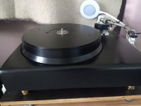
We (Lyra) have been through two Marantz TT-1000 turntables, one original and one MkII.
Marantz TT-1000 | Hifi-Wiki
Marantz TT-1000 II | Hifi-Wiki
Other than recalibrating the motor control circuitry, and checking the spindle bearing, the original has been left largely in stock condition (as it is such a pretty design).
In addition to recalibrating the motor control circuitry and rechecking the bearing, the record mat recess of the stock MkII platter top was milled flat, and a graphite mat bonded to the platter with a permanently non-hardening Loctite adhesive to form a constrained-layer damped construction. The spindle diameter was reduced by a millimeter or so from where it exits the platter, therefore neither the LP center hole nor graphite record mat touch the spindle.
Admittedly the DD motors that Marantz chose for the original and MkII are different, which could affect the sound.
Nevertheless, the isolated-spindle MkII is a much more capable performer than the original version, so much so that the owner of the original version is borrowing the MkII for as long as we don't have an immediate need for it 🙂.
- Home
- Source & Line
- Analogue Source
- Ultimate turntable design: modern technology to remediate root cause issues