That is Tim's "enhanced" mode with a standard cathode bias. This is not a true triode amp as the G1 is influencing the current of the tube here.
Please read my previous entries...
Please read my previous entries...
Last edited:
Thanks Zintolo. Makes sense...I would say make g1 less positive than k, as is needed for it to correctly amplify.
G1 to C. No "grid leak" resistor to ground?Please read my previous entries...
If G1 is connected directly to C then no other connection of the grid anywhere is required as it is shorted to C.
Please read the patent of David Berning:
US3995226A - Audio amplifier
- Google Patents
Please read the patent of David Berning:
US3995226A - Audio amplifier
- Google Patents
I believe you if you say it. I pretty much suck at theory. So I just look at what others do and listen to the result. (Wish I did have a decent electronics background and measurement equipment)
So instead of trying to educate an old lazy dog. Just tell me what you would do. And forget the enhanced triode question. I just thought it was the cat's pyjamas because Tim designed it.
So instead of trying to educate an old lazy dog. Just tell me what you would do. And forget the enhanced triode question. I just thought it was the cat's pyjamas because Tim designed it.
Last edited:
G1 is directly connected to cathode for signal, but is given some negative DC bias. Some valves like some bias on G3, etc. Tweeks. It's a small variation quite possibly introduced to avoid a (bogus) patent fight. They're all the rage in America.
All good fortune,
Chris
All good fortune,
Chris
It all depends on the driver that you are going to implement. If the driver can deliver some current (DC current to the grid so no coupling cap). then you have all options open.
If you decide to use a coupling capacitor on the grid of the power tube you have only 1 option: G1 (the standard).
As you can see in any G2 drivers that these are low impedant drivers (followers of some kind).
In this case you would need a combination tube (in case it is a 2 tube design) like a ECL82/85 etc. or a Mosfet
If you do not like a negative DC driver then you just "lift" the output tube (Tim and Synola etc.). You then need a slightly higher B+ voltage. Or you can choose to have a negative voltage on the driver tube and ground the cathode of the power tube. In this case you need a c between the gain stage (input stage) and the driver stage. This grid of the driver stage will then be you bias regulator as wel as it is DC coupled to the grid of the power tube.
Last edited:
Remember that a tube does not care what ground is or B+ etc. only we do...
As long as the tube gets the voltages between the grid C and A and it can draw enough current it will be fine.. So putting a tube on a high voltage (or even minus) is fine as long as all the other voltages are adjusted accordingly.
As long as the tube gets the voltages between the grid C and A and it can draw enough current it will be fine.. So putting a tube on a high voltage (or even minus) is fine as long as all the other voltages are adjusted accordingly.
G1 is directly connected to cathode for signal, but is given some negative DC bias. Some valves like some bias on G3
Chris
This can be all true but then we do not have a triode in any of these cases, as the grids ARE meddling with the electrode flow within the tube. Only if ALL of the non "drive grids" are "neutralized" (no different potentials) they will not.
David's patent is valid as he states that because of cathode heating the G1 will heat up (more then other grids within a tube) as it is so close to the heat source causing secondary emissions (current can then draw from the grid) causing tube runaway (instability). Therefore using G2 instead of G1 and neutralizing G1 will prolong tube life plus is even more linear and the tubes run cooler. So this idea is interesting) funny that on diyaudio not much is discussed about this as it already an old patent.
Best wishes,
Frank
Good start !
And do not change anything from the original design at first. You can do mods afterwards. The design is good as is.
And do not change anything from the original design at first. You can do mods afterwards. The design is good as is.
Last edited:
Looks nice already...
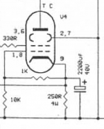
I have build several triode stripped amps (G1 on C) so i have some experience with the bias settings.
Sometime i modify amps to triode operation on request.
The 1st and 2nd pic in this posting makes me curious. This is a pair of PCF80's an EL95's (or PL95's) driving a pair of 807's? Mind to share your schematics, please?
Best regards!
Sent PM
I do not make neat schematics just some scribbling and notes. Then i build and then tune...
I do not make neat schematics just some scribbling and notes. Then i build and then tune...
Last edited:
No grid stoppers either?And do not change anything from the original design at first
Bas quoted (in post #40) the assertion in the UBT-1 transformer flier that “a 13 watt amplifier has been successfully built using a EL509 running 270 volts on the plate, at 150 ma, in ‘enhanced triode’ mode.” My question here - has anyone actually seen this amplifier or schematic? If not how could we get it?
This statement probably originated from John Atwood, the designer of the One Electron transformers. I have always held him in high regard. Given that the One Electron Transformers seem to be defunct, I hope John is OK.
Does anyone have his contact information?
- Home
- Amplifiers
- Tubes / Valves
- How would you drive an EL509 in enhanced triode mode.