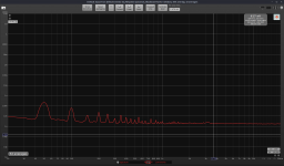
All measurements taken on positive rail at 12volt output, 66mA load, boards upgraded to Rev. A2 except output capacitor changed to Panasonic FC 100uF/63V.
VRDN Positive Rail input Ripple

Positive Rail with stock denoiser disengage noise

Positive Rail with denoiser disengaged output ripple

Positive Rail with stock denoiser engaged noise

Positive Rail with stock denoiser engaged output ripple

Positive Rail Add-on denoiser implemented noise

VRDN Positive Rail input Ripple
Positive Rail with stock denoiser disengage noise
Positive Rail with denoiser disengaged output ripple
Positive Rail with stock denoiser engaged noise
Positive Rail with stock denoiser engaged output ripple
Positive Rail Add-on denoiser implemented noise
Positive Rail Add-on denoiser implemented output ripple

Positive Rail Add-on Dienoiser implemented noise

Positive Rail Dienoiser implemented output ripple

Positive Rail Add-on Dienoiser implemented noise
Positive Rail Dienoiser implemented output ripple
Many interesting links in the first post, thanks for the collection Mark! There seem to be quite a few popular LNA designs which makes it hard to get a good overview in a reasonable amount of time (so many long threads...). Are there any LNAs with published Gerbers apart from the one Samuel Groner designed a while back? I really can't start another design project right now so I am on the lookout for something to just put together and work. Not trying to derail the thread however, I am equally grateful for any PM with a helpful link or hint.
The transformer and VRDN board are about 1 foot apart or 30 centimeters. Nothing is shielded. ...
Still a bit unclear to me RickRay. Do you mean your VRDN pos rail with TI 317 needs a jumper in place of R21 and Panasonic FC 100uF/63v in place of C13 for stable operation?... Positive rail looks like it might be oscillating. Removing the ESR resistor on the negative rail got it to working. I'll wait until I get the capacitors that have been proven to work with the denoiser and I will install those and retest.
Can I get a moderator to delete posts #62 and #63? I'm pretty sure I got the graphs and headings mixed up which will just make things very confusing.
Indra1 - at the point you are referring to, I had Rev. A1 VRDN. After it was changed to Rev. A2 it was stable. I simple changed the output caps because I have had very good luck with those on the positive rail only with denoiser/dienoisers. It will work fine with the caps specified.
All measurements taken on positive rail at 12volt output, 66mA load, boards upgraded to Rev. A2 except output capacitor changed to Panasonic FC 100uF/63V.
VRDN Positive Rail input Ripple

Positive Rail with stock Cadj. noise

Positive Rail with stock Cadj. output ripple

VRDN Positive Rail input Ripple
Positive Rail with stock Cadj. noise
Positive Rail with stock Cadj. output ripple
VRDN with stock denoiser
Positive Rail with stock denoiser engaged noise

Positive Rail with stock denoiser engaged output ripple

Positive Rail with stock denoiser engaged noise
Positive Rail with stock denoiser engaged output ripple
VRDN with Add-on Denoiser
Positive Rail Add-on denoiser implemented noise

Positive Rail Add-on denoiser implemented output ripple

Positive Rail Add-on denoiser implemented noise
Positive Rail Add-on denoiser implemented output ripple
VRDN with Add-on Dienoiser
Positive Rail with Add-on Dienoiser noise

Positive Rail with Add-on Dienoiser output ripple

Positive Rail with Add-on Dienoiser noise
Positive Rail with Add-on Dienoiser output ripple

That was measurement session that included a lot of de soldering/soldering on the four layer board and resulting with interesting data. I suppose you have good de soldering equipment.🙂
Is your measurement setup arranged in a better way as now you measure 100 dB PSRR on stock VRDN board using only 10 mV (-40 dBV) input ripple levels?
What is the difference between noise and PSRR measurement data? On all measurements, noise floor should be at the same level, but it is 5 dB higher on all measurements labeled as ripple, while on both noise and ripple level measurements, 120 Hz ripple is by same value above the noise floor, meaning that in both cases there was load on the output??
In fact, the same measurement can be used to assess both noise and PSRR levels, but which one is right?
Hah, forum automatic filter just warned me that word assess is not written with one 's' letter omitted. 😀
I think in ARTA while measuring PSRR the noisefloor is not to be trusted as shown value. That can vary depending on the FFT resolution. Some others have mentioned this. But the noise should be correct while measuring in the noise density graph. His 1k resistor noise seems to be right as well.
And of-course there's the thing about the differential measurement between the onboard denoiser and the add-on denoiser which should be pretty clear. I think he used the same conditions for these tests, same Vout and load.
Unless you think that he as well is manipulating the data?
And of-course there's the thing about the differential measurement between the onboard denoiser and the add-on denoiser which should be pretty clear. I think he used the same conditions for these tests, same Vout and load.
Unless you think that he as well is manipulating the data?
Many interesting links in the first post, thanks for the collection Mark! There seem to be quite a few popular LNA designs which makes it hard to get a good overview in a reasonable amount of time (so many long threads...). Are there any LNAs with published Gerbers apart from the one Samuel Groner designed a while back? I really can't start another design project right now so I am on the lookout for something to just put together and work. Not trying to derail the thread however, I am equally grateful for any PM with a helpful link or hint.
Build on perfboard, dead-bug or Manhattan style, run on a pair of alkaline batteries --very high quality LNA with an SSM2019 (less than 1nV/RtHz) from Analog. Requires a single gain setting resistor, some input caps, protection and bias resistors. Easy to work with from a few Hz to 100kHz and it's through-hole. Walt Jung used the predecessor part, SSM2017, in his 1995 Audio Express articles which are archived on his website.
If you are aiming to get into the low (hundreds) picoVolt/RtHz you'll have to roll your own.
@Tombo56 - I have an adequate de-soldering solution, I don't think there is such a thing as aa good de-soldering solution. Anyway, I haven't lifted any pads yet. The best way I have found for this board is 375 degree Celsius heat for soldering iron and fine solder braid.
For these measurements I made sure everything on the bench was turned off and everything on the same power circuit turned-off. That was for all measurements in this batch. Other than that, that is what was measured that day.
I mislabeled the noise, it is either dBV/sqrtHz or nV/sqrtHz. That is a noise density measurement that takes into account bandwidth.
Ripple was measured using the dBV scale and if you notice in ARTA, the result at the bottom is labeled as dB.
Of course, these aren't the same scales, so of course they measure differently.
Yes the load was identical in all the tests, 180ohm resistor across the output connector at 12 volts for a 66mA load on all tests. All these tests where ran in the same time period.
You can verify my findings very easily, breadboard a denoiser and connect it to the output of the VRDN. I'm confident that even a breadboard implementation will show an improvement in PSRR. It won't show an improvement in noise. If the denoiser is working, the noise will be at denoiser level. Notice that the noise level between on-board denosier and add-on denoiser are pretty much the same. You've taken enough of these measurements, I think, that you can see those two readings are basically the same because they do drift up and down slightly.
BTW, I'm working on another set of boards with denoisers/dienoisers on them and they are not fairing so well with the soldering/desoldering.
@Tombo56 I believe you are comparing the measurements posted in the VRDN thread when you say I can now measure better. The measurements in the VRDN thread were taken with the wrong calibration. Someone told me to enter 1Volt or .001V if using the LNA, that is completely wrong. You have to calibrate ARTA using a known signal source. After I did that, the correct calibration for my set-up is 3.080V.
When this is used, if I input 1Vrms the dBV scale reads 0dBV, if I place a 1kohm resistor across the input of the LNA, I read approximately 168dBV/sqrtHz or 4nV/sqrtHz.
In other words, I got some bad advice on how to calibrate ARTA.
When this is used, if I input 1Vrms the dBV scale reads 0dBV, if I place a 1kohm resistor across the input of the LNA, I read approximately 168dBV/sqrtHz or 4nV/sqrtHz.
In other words, I got some bad advice on how to calibrate ARTA.
Many interesting links in the first post, thanks for the collection Mark! There seem to be quite a few popular LNA designs which makes it hard to get a good overview in a reasonable amount of time (so many long threads...). Are there any LNAs with published Gerbers apart from the one Samuel Groner designed a while back? I really can't start another design project right now so I am on the lookout for something to just put together and work. Not trying to derail the thread however, I am equally grateful for any PM with a helpful link or hint.
If people want I could make the LNA design public. It's the one that RickRay also used. Should have between 400-570pV/sqrtHz depending on which BJTs you use. You'd need a NE5534A, a TL071 and 3x 2N4403 (or ZTX951) for the LNA circuit. You'd have to match the 3x 2N4403. The power supply uses LM3x7+dienoiser. It's made to be used with a single secondary transformer (24VAC), which could be a wallwart type.
The pcb is diy-able, and I made it to fit an old TA2020 amp case (Muse M20 EX2 written on it). This way I could use the amp's power connector and front switch to switch between polarities. The input connector (BNC/RCA) can be installed instead of the original volume knob. You'd just have to drill a small hole for a thin coax wire used to probe whatever you want to measure.
It also has selectable gain between x10, x20, x50, x100, x200 and x1000.
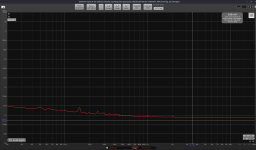
Here's measurements in the latest version of REW, for a 204R resistor noise, and with LNA input shorted. I don't like REW that much, but seems that some only trust REW. I find ARTA to be more practical, and I get the same results in both.
edit: The LF hump is from my ADC, the soundcard on my PC's motherboard. The resistor was on my desk, no shielding for it.
edit: The LF hump is from my ADC, the soundcard on my PC's motherboard. The resistor was on my desk, no shielding for it.
Attachments
Last edited:
- Home
- Amplifiers
- Power Supplies
- Measurement data and techniques for Elvee's De-Noizator: all implementations