BTW, the last measurement was taken with line power to the LNA, the batteries lasted about 4 hours, won't be doing that again.
Here is another measurement of the same thing with the soldering iron turned off. The cord was right over the low input coaxial.

LNA input cable shorted

LNA input cable shorted
and what is above 20kHz?
someone will also use SMPS and let’s say it works at 80kHz or let’s say it’s connected to some DSP or DAC I.C. which produces interference in the MHz band
does this regulator then make sense?
here is an example of how the Japanese do it, from 10Hz to 1MHz
LT3042 Noise Spectral Density nV/√Hzの測定: アナログ回路のおもちゃ箱
ADM7151 vs LT3042 (Output Impedance) by Analog Dicovery: アナログ回路のおもちゃ箱
In the DAC that I designed I put LT3082+denoiser with an LC filter in front, for digital and analog.
LT3042 is expensive and hard to solder.
I attached PSRR and output impedance for LT3082+denoiser.
edit: I replaced the photos for 3.3Vout.
Attachments
Last edited:
Here is another measurement of the same thing with the soldering iron turned off. The cord was right over the low input coaxial.
View attachment 925400
LNA input cable shorted
View attachment 925401
The LNA should be able to measure the denoiser on VRDN. I think they argue that the VRDN board itself picks up noise from the transformer 1 meter away or something like that. I'm not sure if that also is good or not for the VRDN.
But you could really try to add the dienoiser to it, using the add-on boards you have.
I'm waiting on a shipment from Mouser in Texas. The order was placed the 13th and then the whole state shut down because of low temperatures. I'm supposed to get the parts Thursday hopefully.
The transformer and VRDN board are about 1 foot apart or 30 centimeters. Nothing is shielded. Everything in the vicinity is usually turned off. That soldering station creates some issues, LOL.
I did take a look at the output voltage of both rails on the oscilloscope through the LNA.
Positive rail
View attachment bbbbbbbb.bmp
Negative rail
View attachment aaaaaaaa.bmp
Positive rail looks like it might be oscillating. Removing the ESR resistor on the negative rail got it to working. I'll wait until I get the capacitors that have been proven to work with the denoiser and I will install those and retest.
and what is above 20kHz?
someone will also use SMPS and let’s say it works at 80kHz or let’s say it’s connected to some DSP or DAC I.C. which produces interference in the MHz band
does this regulator then make sense?
here is an example of how the Japanese do it, from 10Hz to 1MHz
LT3042 Noise Spectral Density nV/√Hzの測定: アナログ回路のおもちゃ箱
ADM7151 vs LT3042 (Output Impedance) by Analog Dicovery: アナログ回路のおもちゃ箱
LM3x7 has limited bandwidth and denoiser can not change that. Also as has been seen recently the noise of LM3x7+denoiser increases at low voltages. LT30xx, ADM7151 and TPS7Axxx all perform better above 20kHz (even upto 10MHz). LT30xx has the lowest noise of these 3 but the output impedance is a bit higher. It all depends on your requirements. I see no reason to use LM3x7 with DAC ICs.
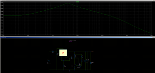
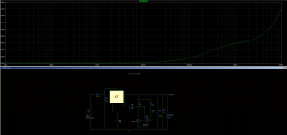
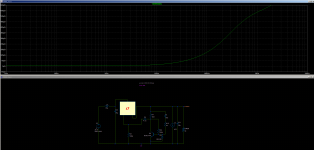
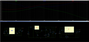
For the curious here's a simulation between LT3042, LT3082 and ADM7150, with 5Vin and 3.3Vout at 100mA, for PSRR and output impedance, just that LT3082 uses a denoiser and a small LC in front.
Not only does the LT3082 arrangement have better PSRR all around the spectrum, but it's in another league of its own for output impedance, at least from simulation.
If I've done something wrong with LT3042/ADM7150 in the sim please correct me, I don't want to present false info. I never worked with them so I only rely on the sim when I say this.
I did measure LT3082+denoiser PSRR at 100Hz these days. Measured a bit worse than sim, still better than the others. edit: I measured PSRR at 12Vout for LT3082+denoiser, might try tot measure at 3.3Vout but sim shows it still should be better.
I still have to do some measurements before I post them, for LT3082+denoiser.
Attachments

Last edited:
I did take a look at the output voltage of both rails on the oscilloscope through the LNA.
Positive rail
View attachment 925466
Negative rail
View attachment 925467
Positive rail looks like it might be oscillating. Removing the ESR resistor on the negative rail got it to working. I'll wait until I get the capacitors that have been proven to work with the denoiser and I will install those and retest.
If you can measure ESR test a few capacitors that you have and choose anything that has around 0.2R. The VRDN total ESR for the positive rails is also wrongly recommended. It should add up to a total of around 0.2R. I think there's a .33R resistor recommended to be added to the output cap on the positive rail. That would come out to around 0.4R to almost 0.5R depending on which of the two output capacitors from BOM you use.
So remove the 0.33R resistor, short the footprint, and use a capacitor with around 0.2R ESR.
Edit: or better yet, add another 0.33R in parallel with the 0.33R already on the board, that should be the easiest way. I think I calculated the ESR to be around 70-80mOhm for the capacitor you use (from tan value). So you should land at around 240mOhm total with cap which should be ok.
Last edited:
I didn't have any .33ohm resistors, so I used .39ohm resistors, two in parallel. That definitely helped. Both pictures are of the positive rail, it comes and goes slightly now, but never looks as bad as the previous picture. I'm betting the recommended capacitor with it's slight inductance fixes the issue completely.
Positive rail
View attachment cccccccc.bmp
View attachment NewFile0.bmp
It took quite a few tries to get the top picture, the scope pattern is usually like the bottom one.
Positive rail
View attachment cccccccc.bmp
View attachment NewFile0.bmp
It took quite a few tries to get the top picture, the scope pattern is usually like the bottom one.
These links from Bonsai have some great information for low-noise design also:
404 Not Found
Ground Loops
404 Not Found
Ground Loops
For low noise instrumentation preamplifiers, such as you might use to measure broadband noise output from a power supply, the circuit designed by Scott Wurcer (3rd link in post #1) is an excellent starting point. Scott is the designer of the AD797 opamp, one of the worlds lowest-noise opamps today ... even though the AD797 product was introduced in 1992. 29 years ago!
For the curious here's a simulation between LT3042, LT3082 and ADM7150, with 5Vin and 3.3Vout at 100mA, for PSRR and output impedance, just that LT3082 uses a denoiser and a small LC in front.
Not only does the LT3082 arrangement have better PSRR all around the spectrum, but it's in another league of its own for output impedance, at least from simulation.
If I've done something wrong with LT3042/ADM7150 in the sim please correct me, I don't want to present false info. I never worked with them so I only rely on the sim when I say this.
I did measure LT3082+denoiser PSRR at 100Hz these days. Measured a bit worse than sim, still better than the others. edit: I measured PSRR at 12Vout for LT3082+denoiser, might try tot measure at 3.3Vout but sim shows it still should be better.
I still have to do some measurements before I post them, for LT3082+denoiser.
I wish to retract this claim, apparently LT3082+denoiser doesn't really work. I gave further explanations in this post:
D-Noizator: a magic active noise canceller to retrofit & upgrade any 317-based V.Reg.
I am sorry for the bad info.
For low noise instrumentation preamplifiers, such as you might use to measure broadband noise output from a power supply, the circuit designed by Scott Wurcer (3rd link in post #1) is an excellent starting point. Scott is the designer of the AD797 opamp, one of the worlds lowest-noise opamps today ... even though the AD797 product was introduced in 1992. 29 years ago!
Do you think the Douglas Self design for the moving coil preamp doesn't work as a 60dB LNA?
The design is the one posted by member Calvin in this post:
Simple 60dB discrete low noise amplifier (lna)
There's also the original article on the design in pdf format, and also a LTSpice sim file.
In the DAC that I designed I put LT3082+denoiser with an LC filter in front, for digital and analog.
LT3042 is expensive and hard to solder.
I attached PSRR and output impedance for LT3082+denoiser.
edit: I replaced the photos for 3.3Vout.
I wanted to point out the method of measurement and the equipment for it.
LT3042 OUTPUT Impedance(2/2): アナログ回路のおもちゃ箱
LT3042 PSRR 測定準備編: アナログ回路のおもちゃ箱
And as for the LT regulators themselves I haven't used them so I don't know how much they really are worth, I use the ADM7150(1) but in digital where it fights MHz interference, but there is better and feasible than that in d.i.y.
There are quite many members here (me included) who have used LT304x, LT3094 or TPS7Axxx with DACs or similar devices. It is relatively easy to get datasheet performance if datasheet recommendations related to e.g. layout are followed. All these regulators have fairly decent performance up to 10MHz.
The Japanese site contains measurements of these regulators so there is no need to do any simulations when comparing these to e.g. denoisers.
BTW their logo has a hilarious spelling mistake 😀
The Japanese site contains measurements of these regulators so there is no need to do any simulations when comparing these to e.g. denoisers.
BTW their logo has a hilarious spelling mistake 😀
- Home
- Amplifiers
- Power Supplies
- Measurement data and techniques for Elvee's De-Noizator: all implementations