This thread allows members to share their knowledge and experience with measurements on various physical implementations of Elvee's De-Noiser circuits: LINK TO ORIGINAL
Posts in this thread can include, but are not limited to, measuring tools, software setups, measurement techniques, instrument circuit design, instrument calibration, and of course, measured data itself.
Here are a few links to Forum posts, and to external technical papers, which can be of use to experimenters who work on these circuits and use this kind of measuring gear:
https://www.diyaudio.com/forums/software-tools/338511-howto-distortion-measurements-rew.html
https://www.diyaudio.com/forums/software-tools/360634-interpretation-measurements-rew.html
https://www.diyaudio.com/forums/equ...1000-low-noise-measurement-amp-ikoflexer.html
The L|A Autoranger | Linear Audio NL
https://linearaudio.net/article-detail/2113
https://www.analog.com/media/en/technical-documentation/application-notes/an124f.pdf
https://www.analog.com/media/en/technical-documentation/application-notes/an-940.pdf
https://sci-hub.se/10.1049/ree.1968.0059
http://www.keith-snook.info/wireles...ntroduction to low-noise amplifier design.pdf
http://www.janascard.cz/PDF/Design of ultra low noise amplifiers.pdf
https://sci-hub.se/10.1063/1.1140285
https://pdfs.semanticscholar.org/d770/d93b92abf067aab6e469ba816da0d205777e.pdf
http://www.keith-snook.info/wireles...2/Low-noise Audio Amplifiers - H P Walker.pdf
@RickRay
Following discussion from the VRDN thread and last set of measurements:
https://www.diyaudio.com/forums/pow...ts-11v-20v-1-5a-de-noiser-50.html#post6543468
Was calibration right for test with transformer on and VRDN disconnected? If I do the similar, under the desk transformer will show at -130 dBV at 50 Hz, and -160 dBV for the 100 Hz from the nearby rectifier, but fft “grass” is at – 175 dBV.
If everything was right, it is clear that you can’t get real PSRR results due to very strong EMI. Your LNA is picking environment noise at -120 to -130 dBV. Powered on VRDN regulator will shunt most of that but some effect will remain.
I'm not sure what exactly is to be done in REW. I can't get it to run in Linux with Wine, and I also don't think I can correctly calibrate it as I have no gain controls for my audio card.
There is a Linux installation of REW available as well. The calibration in REW is done in a similar way as in ARTA (i.e. feed measured signal to soundcard and REW calculates the FS voltage). No soundcard gain controls are required. I use REW with soundcards with or without gain controls.
For measurements I prefer not to have gain controls as they can easily mess the calibration. Also on some soundcards the gain control implementation is not "transparent".
@RickRay
Have you measured the ripple of you LNA with input shorted? That would be an indication of how much noise your LNA has or is picking from the environment. That LNA ripple may be partly what you measurements are showing for VRDN output ripple since after denoiser the VRDN output ripple may be lower of the two.
Have you measured the ripple of you LNA with input shorted? That would be an indication of how much noise your LNA has or is picking from the environment. That LNA ripple may be partly what you measurements are showing for VRDN output ripple since after denoiser the VRDN output ripple may be lower of the two.
Calibration measurement with 1 kΩ resistor should be enough confirmation that 120 Hz noise is not from LNA power supplies or that LNA is directly picking up EMI:
https://www.diyaudio.com/forums/pow...ts-11v-20v-1-5a-de-noiser-40.html#post6538842
Adding connection cables to the DUT changes everything.
I was also experimenting with placing DUT inside various cookies thin box, single and double. That was a good excuse to eat a lot of fine cookies.
It didn’t help a lot for EMI levels in my case, except I felt happier after eating all those cookies.
You are probably correct regarding LNA ripple so it must be well shielded.
Looking at the latest measurements by RickRay (see here) it seems that with higher input ripple the output ripple stays the same and PSRR has increased. It may be that the input ripple was still not high enough to show the real PSRR of the VRDN board.
Looking at the latest measurements by RickRay (see here) it seems that with higher input ripple the output ripple stays the same and PSRR has increased. It may be that the input ripple was still not high enough to show the real PSRR of the VRDN board.
It may be that the input ripple was still not high enough to show the real PSRR of the VRDN board.
How come? He was able to measure the 1k resistor noise which is lower than the output ripple of the board. So that means that his measurement setup is able to go low enough to correctly measure the output ripple, which is higher than the noise floor of a 1k resistor.
You need to consider that he basically modified the board, he used an external bridge rectifier, removed part of input capacitance from the circuit and had a different ground point from the external bridge, on the pcb. This is not a stock VRDN measurement anymore, and the increase in measured performance is not on a stock VRDN board.
The 1k resistor noise measurement was made with just the LNA and soundcard. Looking at measurements in post #492 and in post #508 the output ripple is almost the same even though the input ripple has increased by 10dBV in the latter. So it seems that the output ripple is close to the measurement limit when VRDN is measured. This may be due to EMI as suggested by Tombo56.
The output ripple actually decreased in value.
What does measurement limit mean as I don't understand that. He could measure a 1k resistor noise which is lower. We can also see the denoiser noisefloor which is lower than the output ripple. Why would he be able to measure the lower noisefloor of the denoiser and not the output ripple.
Also his first measurement, before disconnecting the first capacitor bank from the CRC, between Cadj and denoiser, shows a correct PSRR for Cadj. It's only when the denoiser is connected that we don't get the expected results. We do see its correct noisefloor, you all agreed on it. But somehow RickRay's measurement setup cannot measure the output ripple? Even if he can measure the correct noisefloor which is lower than the output ripple?
This isn't about noise. This is about PSRR and grounding that affects it. Especially in the case of the denoiser which was invented by Elvee, and he had a series of recommendations about it, which were not respected in the VRDN's grounding layout.
That + measured results paint a pretty clear picture.
That + measured results paint a pretty clear picture.
The output ripple actually decreased in value.
What does measurement limit mean as I don't understand that. He could measure a 1k resistor noise which is lower. We can also see the denoiser noisefloor which is lower than the output ripple. Why would he be able to measure the lower noisefloor of the denoiser and not the output ripple.
Also his first measurement, before disconnecting the first capacitor bank from the CRC, between Cadj and denoiser, shows a correct PSRR for Cadj. It's only when the denoiser is connected that we don't get the expected results. We do see its correct noisefloor, you all agreed on it. But somehow RickRay's measurement setup cannot measure the output ripple? Even if he can measure the correct noisefloor which is lower than the output ripple?
The output ripple decreased by less than 1 dBV which may be due to even a small change in the environment (e.g. nearby device turned on/off).
For the rest maybe you should study post #2.
I'm pretty sure the positive rail is still unstable. I am measuring the output ripple on the negative rail and it is around 1.4Vp-p and then drops to 80mVp-p, this would also be x1000, I'm using the LNA on my scope. When it's at 1.4V you can see a distinct sine wave.
It fluctuates between these two reading every couple seconds.
It fluctuates between these two reading every couple seconds.
Why are you considering the last measurement RickRay made as being illustrative of VRDN type performance? He didn't measure a VRDN stock board, he affected the grounding. What he did is a pretty serious modification, you can't possibly consider it as representative of VRDN performance.
Also the measured Cadj values seem perfectly reasonable (on stock VRDN), are you arguing that the -15dB or so decrease from the denoiser are pushing everything into a measurement area where it's hard to correctly measure the board?
You already agreed his LNA is well shielded, we have my measurements which clearly show it being able to read lower output ripple.
So after all this, the conclusion is that he just can't correctly measure the VRDN?
At this point this is weapons grade hopium.
If you want to try something fun you could add those denoiser add-on boards to the VRDN. Remove Cadj and tap the ADJ connection for LM3x7. You also can configure it for dienoiser for better performance. Might be a worthwhile upgrade to the VRDN. Since it's an add-on you can place it such that you get the max performance out of it. For the dienoiser I strongly suggest you install the Panasonic FC for positive and FR for negative output caps.
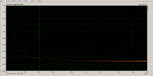
I measured my LM317 board with the capacitance multiplier installed. I measured the denoiser and also the dienoiser. 11.4Vout with 150R load.
As can be seen, the ripple is under the noisefloor. For dienoiser at 100Hz measures -157.75dB with 1.3V for 0dB.
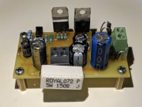
I had my LNA transformer on the desk about 50cm away from the pcb. No shielding for the pcb, it sat on the desk as you see it in the picture.
RickRay has his 0dB set at 2.16V in ARTA, which means a difference of around 4.4dB vs my 0dB point. So he should be able to go at least to -162dB for ripple measurement, on his graph.
Now, the VRDN is larger and I think it theoretically may pick up some noise that could theoretically interfere with the measurement. I'm not sure how much, I had a powered transformer 50cm away from the pcb. The transformer was naked on the desk, no case or shielding.
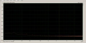
1st photo is measurement of dienoiser with capacitance multiplier in circuit, second is the noise for the dienoiser. I used a ST LM317.
So ok, I'll give the VRDN that, it could theoretically work in spec for denoiser but it might be too complicated to test with the high input capacitance.
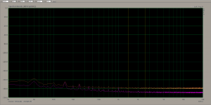
edit: also added a comparison between the LNA noisefloor vs dienoiser noisefloor, for the last picture.
As can be seen, the ripple is under the noisefloor. For dienoiser at 100Hz measures -157.75dB with 1.3V for 0dB.
I had my LNA transformer on the desk about 50cm away from the pcb. No shielding for the pcb, it sat on the desk as you see it in the picture.
RickRay has his 0dB set at 2.16V in ARTA, which means a difference of around 4.4dB vs my 0dB point. So he should be able to go at least to -162dB for ripple measurement, on his graph.
Now, the VRDN is larger and I think it theoretically may pick up some noise that could theoretically interfere with the measurement. I'm not sure how much, I had a powered transformer 50cm away from the pcb. The transformer was naked on the desk, no case or shielding.
1st photo is measurement of dienoiser with capacitance multiplier in circuit, second is the noise for the dienoiser. I used a ST LM317.
So ok, I'll give the VRDN that, it could theoretically work in spec for denoiser but it might be too complicated to test with the high input capacitance.
edit: also added a comparison between the LNA noisefloor vs dienoiser noisefloor, for the last picture.
Attachments
Last edited:
and what is above 20kHz?
someone will also use SMPS and let’s say it works at 80kHz or let’s say it’s connected to some DSP or DAC I.C. which produces interference in the MHz band
does this regulator then make sense?
here is an example of how the Japanese do it, from 10Hz to 1MHz
LT3042 Noise Spectral Density nV/√Hzの測定: アナログ回路のおもちゃ箱
ADM7151 vs LT3042 (Output Impedance) by Analog Dicovery: アナログ回路のおもちゃ箱
Just as suspected, I had it set to 1V instead of .001, I think. Anyway, I redid the Tombo measurement and it makes much more sense now. I am also using the snipping tool instead of the photo taker in REW, the REW thing doesn't give all the info on the screen.

There is nothing wrong with my measurement set-up, it is working perfectly.
There is nothing wrong with my measurement set-up, it is working perfectly.
- Status
- This old topic is closed. If you want to reopen this topic, contact a moderator using the "Report Post" button.
- Home
- Amplifiers
- Power Supplies
- Measurement data and techniques for Elvee's De-Noizator: all implementations