I think that FS sine rms is a multiplier value. You set it for 0.001 because the LNA has 1000x gain. So 1000 x 0.001V= 1V.
You change the FS sine rms value if you change the gain of the LNA. Else I don't know why you'd change that.
I'm not sure what exactly is to be done in REW. I can't get it to run in Linux with Wine, and I also don't think I can correctly calibrate it as I have no gain controls for my audio card.
Why do you change the 0.001V value?
Huh, you can't measure 1 K resistor noise directly with Focusrite!
It's noise level is far far above noise of that resistor. That's why you need LNA.
So, there is a mistake in the procedure. Your calibration for the 1 V level was wrong.
It's oscilloscope that is needed in the end.
It's noise level is far far above noise of that resistor. That's why you need LNA.
So, there is a mistake in the procedure. Your calibration for the 1 V level was wrong.
It's oscilloscope that is needed in the end.
You'd get an increase in ripple so this would be good if you could take out the first 6600uF from the circuit.6600uf before resistors, 4400uF after resistors.
It's oscilloscope that is needed in the end.
Are you saying that you just can't use the ADC to sense the input ripple? Are you stading by this statement?
If you sense the input ripple with the ADC, then output ripple with the LNA+ADC, this will result in a measurement that could be off by let's say 17dB? As long as 1k resistor noise connected to LNA gets the correct result if LNA signal is fed into the ADC?
Last edited:
@tombo56 your explanation makes sense. What I actually did when I made the measurements was calibrated with 1k resistor with FS sine rms set at .001V.
When I changed to measuring input ripple, I didn't recalibrate, I simple changed FS sine rms to 1V. I think the measurement are still valid.
I was trying to verify 1000 times gain and your explanation about ADC noise explains why it couldn't measure the 1k reisitor noise directly.
When I changed to measuring input ripple, I didn't recalibrate, I simple changed FS sine rms to 1V. I think the measurement are still valid.
I was trying to verify 1000 times gain and your explanation about ADC noise explains why it couldn't measure the 1k reisitor noise directly.
still not sure the LNA is working correctly.
When you calibrated your 0dB point in ARTA, you used your signal generator to input a known signal into your ADC. After ARTA estimated your 0dB point, you connected your LNA with a 1k resistor connected on the input and ARTA measured its noise exactly as expected to be, related to your 0dB point.
You might be having some issues, maybe even the LNA not working. But it's the same one I'm using, and I'm getting measurement results that are consistent with LTSpice simulations. If there were issues with absolute measurements I expect them to be in the 1-2dB range, not 17dB.
Does everyone agree that if I calibrate with FS sine rms set at .001V and adjust so 1kHz reading =-168dBV, that measurement should be accurate?
Second question, if I simple change FS sine rms setting to 1V and don't touch gain, that measurement would be accurate without LNA in measrement path?
Second question, if I simple change FS sine rms setting to 1V and don't touch gain, that measurement would be accurate without LNA in measrement path?
@tombo56 your explanation makes sense. What I actually did when I made the measurements was calibrated with 1k resistor with FS sine rms set at .001V.
When I changed to measuring input ripple, I didn't recalibrate, I simple changed FS sine rms to 1V. I think the measurement are still valid.
I was trying to verify 1000 times gain and your explanation about ADC noise explains why it couldn't measure the 1k reisitor noise directly.
You don't need to recalibrate, the LNA just ads 60dB to any signal fed into it. So when you measure without using the LNA, you change just the multiplier, without recalibrating. Calibration is just for the ADC.
In ARTA you calibrated your ADC with a known signal, then when you added the LNA and measured a 1k resistor noise, the result was exactly what it should have been. Theoretically the LNA just adds 60dB to anything on its input.
@Trileru Tombo's explanation about the noise level explains why I couldn't measure resistor directly without LNA. That's the reason we needed an LNA in first place, I should have realized that.
You don't need to recalibrate, the LNA just ads 60dB to any signal fed into it. So when you measure without using the LNA, you change just the multiplier, without recalibrating. Calibration is just for the ADC.
In ARTA you calibrated your ADC with a known signal, then when you added the LNA and measured a 1k resistor noise, the result was exactly what it should have been. Theoretically the LNA just adds 60dB to anything on its input.
I agree and that is the procedure I used for the measurements I posted. I mis-stated I recalibrated with 1V level, I did not.
You can remove the R from CRC, you'd cut on the input capacitance and have higher ripple on input/output.
Then you measure input ripple (don't forget to set your multiplier to 1x), then the output with LNA and set your multiplier 1000X. This both in REW and ARTA. You should get the same result from both, for PSRR.
You calibrate in REW with the 1k resistor, you use your calibration value that ARTA found, in ARTA, without adjusting the gain knob in ARTA.
This differential method should give a good idea about PSRR, even if off by 1-2dB.
To be even more clear, you add another measurement to the two you'll make (input/output ripple). You disconnect the denoiser, and use the Cadj mode, and you measure the output ripple on that mode as well. So input ripple without LNA, output ripple with Cadj and LNA, and output ripple with denoiser and LNA. And both in REW and ARTA so you're sure about your results.
This will show the total PSRR with denoiser, and also how much the denoiser attenuates the ripple vs Cadj.
Last edited:
I changed my LNA to be powered by 4 9V batteries. I measured just the positive rail.
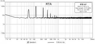
Positive rail noise density

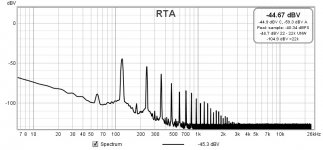
Positive rail input ripple

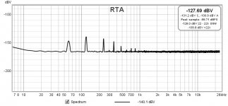
Positive rail output ripple

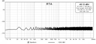
Tombo suggestion - transformer powered but not hooked to VRDN board

PSRR @120Hz still measures -94.8dBV
Noise density improved more than likely because of changing to battery powered LNA.
Positive rail noise density

Positive rail input ripple

Positive rail output ripple

Tombo suggestion - transformer powered but not hooked to VRDN board

PSRR @120Hz still measures -94.8dBV
Noise density improved more than likely because of changing to battery powered LNA.
This still set to 12V with 66mA load. BTW the noise density didn't improve, measured almost the same, 4.87nV before 5.0nV9 this time.
My LNA's noise came out at around 0.6nV/sqrtHz and if I remember right yours came out at around 0.46nV/sqrtHz as you're using those low noise ZTX BJTs for the LNA circuit. I don't think it affects the noise of the regulator board output, which seems around the 8nV/sqrtHz value on most of the spectrum.
Agree and I'm not seeing any real improvement with measurements from line powered to battery powered.
Am I missing something?
I'm feeding the battery power through the regulators and the denoiser on the LNA board.
Am I missing something?
I'm feeding the battery power through the regulators and the denoiser on the LNA board.
Maybe try to connect the voltage on the output of the regulators. But you'd have to make other modifications to account for the voltage difference, I think.
The opamps in the LNA have PSRR and the BJTs have an RC filter between their collectors and negative rail. I wouldn't really stress about this really. The noise is not the issue here.
When you have time you can remove the R from CRC, and connect the secondary of the transformer to a bridge rectifier, and then connect the GND output of the bridge to a GND point on the second C from CRC, and connect the +V of the bridge to the hole left by the R, on the second C side. This way you cut the first 6600uF from the cap filter bank. That should increase the ripple on the input/output.
Measuring this way, (also with Cadj version) should make things more clear. Focus on PSRR not noise.
I'll start with a Cadj measurement (denoiser shorted) first. I can do that without significant mods.
Instead of removing resistors, could I solder a jumper from the input of the first set of caps to the input of the second set of caps? That would skip the first set of caps and the resistors. That would be way easier if you all think that would work the same.
You should measure Cadj after you do the capacitor mod. So you have the same input ripple. You want to compare Cadj to denoiser on the same input ripple.
If you short the resistor you'd parallel all of them. It doesn't solve the issue.
You can't use the onboard bridge and first bank of capacitors. You have to have an external bridge and to remove the resistor, and solder the Vout of the bridge on the second C side of the CRC, in the hole that the resistor left. And ground the other connection of the bridge (GND), to the first capacitor ground from the second C from CRC.
- Home
- Amplifiers
- Power Supplies
- VRDN: bipolar regulator PCB for line level ckts: ±11V to ±20V @ 1.5A with "De-Noiser"