@indra1 If you follow Rev. A2 for either regulator, it should not oscillate and should have less than 10nV/sqrtHz noise at the output.
Available VRDN PCBs
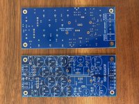
I just took delivery on VRDN boards and PCBWay sent me quite a few more than I ordered. I have all that I need now for my current project, plus these few more, so thought I'd offer the extras up here.
Blue boards, well-made, 2 oz. copper. Just charging what I paid plus postage - $10.00 each (via PayPal) shipped anywhere in the US.
PM me if you're interested. Include your PayPal info and how many boards you'd like and I'll get an invoice to you for payment.
Thanks,
Brad
Attachments
Inrush Current Limiter on VRDN
I'm building Wayne's BA18 preamp and using two VRDNs for a dual-mono power supply. I'll use two 25VA/18V transformers, one for each board.
Do I need and ICL on each of these? I'm trying to figure out the appropriate values for them, but if it's not necessary in this build, I'll just skip them.
Also, is it a good idea to put a safety cap after the switch, based on how I'm building the power supply?
I used two VRDNs on the WBA 2018 and didn't need an inrush current limiter with two 50 va 18 volt transformers.
Hello,
What is the minimum voltage drop for the regulator and denoiser circuit to work optimally?
Does this power supply follow the transformer secondary voltage x 1.414 calculation prior to the regulator? I am trying to figure out if I could use 15 volt secondaries and get enough voltage drop for a power supply output of between 17 and 18 volts.
Thanks in advance for any feedback,
Alan
It's a plain ordinary LM317 regulator using plain ordinary diodes and capacitors, you analyze it the same way you analyze every other LM317 circuit. The "de noiser" has no impact upon input-to-output voltage drop.
PCP traces, grounds
Hi my friends
I just had a peek at the PCB-layers to see if I'd be able to understand if... the ground-plane is one for all or if they are one per channel...
One for all is correct, isn't it, and this it is sufficient to have just one connection per channel of the line-stage? (and not VRDN-neg, VRDN-pos per channel)
thank you!
david
Does it make it worse to use a 3300uF cap after the VRDN?
We had the oscillation issue and that's what i did to cure it, runs stable ow, but I did not do extensive testing on the output wave form.
At some point i might go back and swap chips and do some of the upgrade/stability tweaks offered up after we ran unto the issue, but it's way down the list at this point.
Low voltage output VRDN
Hi Mark,
as you said repeatedly, this VRDN is based on a straight forward LM317/337 circuit. Why then is the voltage at low end limited to +/-11V? I cannot see a Zener or other ref voltage which in other regulators is a limitation for the output voltage range. Do I need to do changes of the components to go to +/-5V (others than the usual ones) ? Other reasons why you wouldn't use the 317/337 for low voltage?
It's your PCB, you own it. Please feel free to stuff and solder it with whatever components you wish. If you use the components and component values shown in post #1 you'll get an output voltage of ±11V to ±20V as you turn the trimmer potentiometer knob from full anti-clockwise to full clockwise. That was my guess about what 98% of all line level circuits would probably want: 12V up to 18V, with a little cushion on both ends of the range. If I guessed wrong for your line level audio circuits, I'm sorry.
If you need regulated voltages less than 11V you can either use a different PCB, one which has been designed and tested and characterized for 5V outputs; or you can calculate new resistor values and new trimpot values for the regulator ICs on this board, plus new resistor values & capacitor values for the Denoiser. The Denoiser can be a source of instability, there are scope photos in this thread of it oscillating(!). That means you'll want to run a lot of checks with a scope and a high current pulse generator, to make sure that your 5V Denoisers (plus and minus) are performing acceptably.
edit- Whoops, I forgot to mention a third option: You can disable the Denoisers using the provided jumpers, which completely removes them from the active circuit. Then you only need to redesign the resistors & trimpots surrounding the regulator ICs.
_
Last edited:
Low voltage output VRDN
Thanks Mark,
thats the comment I was looking for. So of course, it's more than just adapting R7/R8/R11. Your last comment certainly is not an option others than using J3 for testing purpose. I will need both, +/-15V and +/-5V so I will play and if I cannot get the 5V output quiet you still can change to lower noise regulators.
- Home
- Amplifiers
- Power Supplies
- VRDN: bipolar regulator PCB for line level ckts: ±11V to ±20V @ 1.5A with "De-Noiser"