On a sinusoidal signal in a steady state (as we usually measure with Audioprecision), we will not see anything, since we measure the average distortion, say, at the 1000th and further period.
But the music signal is not a sinusoid, it is constantly changing and OOS is constantly trying to pull up the output signal to the original with a signal propagation delay. The less this delay is, the more accurate the signal amplification will be. It was not for nothing that I brought the work of the filter on switched capacitors, which perfectly fulfills its function on stationary signals, but as soon as a multi-tone signal arrives, its work deteriorates 1000 times. So it is here.
So why show a sinus at all in all your simulations - music don't start with a sinus.
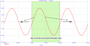
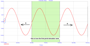
But please answer my specific question above - in the case the second cycle is also a sinus - what does the corresponding part that your show to be affected in the first cycle, look like. Answer this, please.
//
I played with LT to simulate this FB delay error and came to this.
I know the 10us is unreal I just simulated it out of curiuosity and as a magnifier of this theoretical case.
BTW I didn't found any advice on the net: soneone knows how to use a losless delay line in LT?
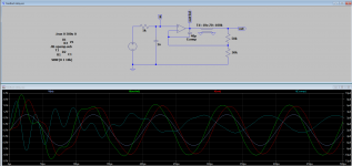
Elements in the layout:
Input signal:
Ideal opamp:
(False?) conclusions:
But I'm sure I made some errors so feel free to correct this experiment. 😱
I know the 10us is unreal I just simulated it out of curiuosity and as a magnifier of this theoretical case.
BTW I didn't found any advice on the net: soneone knows how to use a losless delay line in LT?
Elements in the layout:
- 1k + 1n input RC filter
- 40p compensation (otherwise it oscillates)
- tline: 10us delay (100k impedance to match the FB load)
- FB ratio = 1/2
Input signal:
- f = 10kHz
- A = 2Vpp
Ideal opamp:
- Aol = 5
- BBW = 50MHz
(False?) conclusions:
- if the delay is significant, then after a "new" transient change the system distorts at the beginning and has to settle on the first few periods
But I'm sure I made some errors so feel free to correct this experiment. 😱
Attachments
@Cortez
You can throw out the delay line, it's unnecessary. Change the parameters of the amplifier itself with a compensation capacitor - this will be enough. Petrov uses a delay line to compensate for the delay in the amplifier itself, so that the output signal can then be subtracted from the input signal at the appropriate scale. If you don't, you don't need a delay line.
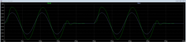
Don't overload the graph with curves. For example, V(out-bd) can now be discarded) And the diagram above the graph is convenient, do not give up on this if possible.
You can throw out the delay line, it's unnecessary. Change the parameters of the amplifier itself with a compensation capacitor - this will be enough. Petrov uses a delay line to compensate for the delay in the amplifier itself, so that the output signal can then be subtracted from the input signal at the appropriate scale. If you don't, you don't need a delay line.
Don't overload the graph with curves. For example, V(out-bd) can now be discarded) And the diagram above the graph is convenient, do not give up on this if possible.
By the way I'm starting to believe that there is some "middleway" about this starting phenomena between the 2 "counter-camp" stated untill now.
I mean of course it's unreal (in the audioband and in practice as well) that a signal starts from 0 with an infinite speed (step signal test).
But I guess the very same is exactly true when we deal with just perfectly continuous (amplitude, phase, frequency) sine waves "with history".
In my simulations a 10kHz sine was starting from zero but via a 1k-1n LP filter.
Would this also be a hugely unreal kind of starting transient signal which can't be present in music..? 😕
Let's come at it from the other end, what is the minimum time interval that we can perceive, and I'm not referring to interaural time difference?
I (of course) completely admit that I/we don't know...
It's just a phenomena that may exists and maybe worth to consider.
But that's also true for almost every little effort we make to gain some new 0.000x% THD improvements.
And I guess everyone would come to peace if we'd say: yes, there is a FCD but...
PS: wow, there is a LCD as well... a Last Cycle Distortion... 😀
It's just a phenomena that may exists and maybe worth to consider.
But that's also true for almost every little effort we make to gain some new 0.000x% THD improvements.
And I guess everyone would come to peace if we'd say: yes, there is a FCD but...
- it's not that much (as the delay is never this big)
- even if it's there it doesn't have any impact on the sound and we don't hear it
PS: wow, there is a LCD as well... a Last Cycle Distortion... 😀
Attachments
Last edited:
It has not been shown that measurement of FCD could bring anything not revealed by other established measured parameters such as slew rate, GBW, gain margin, phase margin, propagation delay and a few others. Why bother?... It's just a phenomena that may exists and maybe worth to consider...
Why is everyone so against FCD? Because this is an unnecessary concept that can be adequately described in the framework of classical terms. It's just that Petrov is fixated on this and no longer accepts critical comments. They cause a defensive reaction in him, not a comprehension and thought process. When he realizes what a trap he has fallen into and thinks carefully, he will understand that there are no enemies around and it turns out that all the negativity is not worth a eaten egg (I hope there is a similar expression in English).
Why does the first period curve in the simulator? When the input signal is applied, the simulator does not know what it has at the output. It has made a preliminary calculation for direct current and then enters an alternating signal. Since the input signal has been received, but there is still nothing at the output, the differential voltage between the inverting and non-inverting outputs increases until the time required for the signal to appear at the output has passed. During this time, the amplifier is not in operating mode and it is impossible to judge its quality indicators and sound. This mode is similar to the experiment that Damir suggested earlier in the topic. This is a transitional process, nothing more.
This can happen in the middle of the simulation if we stimulate the input with a fast signal with a high slew rate in any form, explicit or implicit. It can be a square wave, it can be a sine burst (a sine modulated by a square signal).
As an example, I deliberately took a DC amplifier to minimize transients.
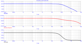
The Bode diagram shows that the group delay is constant from fractions of a Hz to several kHz instead of the necessary 200 kHz to obtain negligible distortions.
The output voltage after external influence returns to normal state only after 6.3 μs. At the initial moment (when the external voltage is close to zero), the output resistance is maximum and is several times higher than the resistance in the steady state.
Attachments
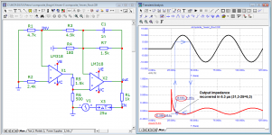
Here we go again. Petrov sent a step signal to the output of the amplifier, which the object will be able to compensate only after passing through the amplification stages to the output. But in normal operation, this does not happen. To produce a sharp surge of voltage, the speaker system must have a speed-appropriate mechanical stimulus. And there is a natural question-where did it come from and whether this is a normal mode? Do you use a wooden hammer to knock on the speaker membrane?The output voltage after external influence returns to normal state only after 6.3 μs. At the initial moment (when the external voltage is close to zero), the output resistance is maximum and is several times higher than the resistance in the steady state.
Why bother?
Why is everyone so against FCD?
Because this is an unnecessary concept that can be adequately described in the framework of classical terms.
Ok I understand. I see it as just a "magnifier" tool not to forget about the aspect of the relevance of the group delay.
For example: someone says why to decrease it? Or why to bother with a better HF compensation?
Maybe then it could be a bit more illustrative if one would see its impact on the very first sinewave for example.
But I agree that it's a bit misleading when showing it with an ideal step response.
I also just "tuned" the delay to 5us for presentational reasons to magnify the effect what is there obviously.
Reducing the group delay corresponds to an increase in GBP and allows you to get more NFB at high frequencies with the right compensation. This, in turn, allows to decrease distortions. So everything is perfectly consistent with the classical theory. You can make more GBP and not get problems with stability and stability-do it, because no one will beat your hands.🙂 However, the parasitic subtleties of installation and other nuances of implementation in hardware impose their limitations and you need to be realistic.For example: someone says why to decrease it? Or why to bother with a better HF compensation?
Maybe then it could be a bit more illustrative if one would see its impact on the very first sinewave for example.
I have already shown, I am showing againBut please answer my specific question above - in the case the second cycle is also a sinus - what does the corresponding part that your show to be affected in the first cycle, look like. Answer this, please.
//
Attachments
I guess this FCD idea isn't against the classical theory at all but it's rather on the topic how we measure the total/final distortion.So everything is perfectly consistent with the classical theory.
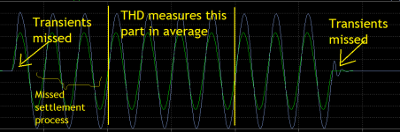
So it's max "against" using the THD method exclusively, because it doesn't measure
this begining and the ending part "just" the middle and also that in average.
So if we have any additional dynamic, transient distortion before or after that it will be missed.
(Or even in the middle if it's modulated somehow...)
Attachments
Last edited:
This is what you show how the signal would look if you copy the pieces that fall into the time window of the analysis. But this is not the case in reality.I have already shown, I am showing again

I will repeat once again - distortions similar to those shown by Petrov occur only when the input stage is overloaded with a differential input signal, or in other words, when the input signal is faster than the output amplifier can handle with the required scale. In normal mode, this should not happen if the designer has the necessary knowledge and has developed an amplifier without errors. And it's not about the presence of modulation or its absence. I have already written enough posts with my colleagues above to make it clear - just read them carefully.I guess this FCD idea isn't against the theory at all but it's rather on the topic how we measure the total/final distortion.
So it's max "against" using the THD method exclusively, because it doesn't measure
this begining and the ending part "just" the middle and also that in average.
So if we have any additional dynamic, transient distortion before or after that it will be missed.
(Or even in the middle if it's modulated somehow...)
The IMD and THD tests are not intended to detect linear distortions, since linear distortions are determined by the amplitude and phase characteristics with a closed feedback loop.
Ok, I can accept this. 😛this should not happen if the designer has the necessary knowledge and has developed an amplifier without errors
Petrov: what do you say? Can you show an example when there is FCD
present with a normal starting speed signal in a well designed average amplifier?
- Home
- Amplifiers
- Solid State
- First cycle distortion - Graham, what is that?