And can the group delay (in reality not in sim and) in transient (not continuous AC) mode have a changing value?
For example depending on temperature, voltage level, etc.
For example depending on temperature, voltage level, etc.
Short answer: for all practical purposes, no.
Long answer: The Earth rotation period also changes with the distance to Saturn.
So the right questions are:
Q1: do the group delay (in reality not in sim and) changes in transient (not continuous AC) mode matter in an audio amplifier?
A1: no, except for those claiming they can hear them. Under uncontrolled conditions, of course.
Q2: can we measure such changes?
A2: yes, if somebody could prove first they would matter for better audio. And for the right price, of course.
Thanks syn!
And can the load (I mean a real, reactive speaker for example) have an impact on the feedback a similar way as if the GD would be changing?
I mean like when there is a capacitive load under testing and a ringing appears.
Or the real world conditions (RL @ output + normal speaker as a load, etc) are in a well defined range and so it never happens?
In your opinion, what is highlighted in yellow I created myself
This seems to mirror what Maynard described as FCD and looks like it came from a simulation most likely due to him.
I have never seen the aberration depicted in your image for sine wave input - whether from the input signal generator or the output for any circuit anyone has simulated in LT SPICE.
It is time you stopped crusading for a lost cause.
If one is looking for transient response it is better to use a square wave and work out the frequency from the inverse result for rise time.
One could describe sine waves as low speed steady state transients with warps. Music is transient and not like that.
One could describe sine waves as low speed steady state transients with warps. Music is transient and not like that.
If one is looking for transient response it is better to use a square wave and work out the frequency from the inverse result for rise time.
A transient can be described as a signal with a beginning and end. It seems the most informative way to observe the character of transients is to use a square wave of frequency that can contain the beginning and end points of the transient (high or low frequency). To do otherwise is to engage in a need to interpret the contribution of some perhaps convoluted input stimulus to the totality of the observed output as containing that transient.
Back in the early 1970's a friend loaned me an LP with the Anne Elk interview sketch on one track. Just like that this thread is getting irksome.
This discussion could easily be solved if just Petr invites all involved to listen to the resuls of his remedy
Cheers!
Cheers!
Best to wait till the bicyclegirls start to be bare-legged again, if it will be in Northern part of Russia. Allthough I look pretty amazing in my bearskin hat.
Cheers and happy new year to all of you good people.
Cheers and happy new year to all of you good people.
Guerilla, none of those who have approached me with a request to help cure a vintage amplifier have complained that they wasted their time on improving the amplifier according to my recommendations. I only get thanks ... So keep your sarcasm to yourself.
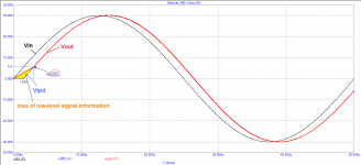
Let's simulate an ideal transient-free follower with a signal propagation delay of 1.5 μs and see the output signal (red). The input voltage is shown with black line, blue line shows the input voltage delayed by 1.5 μs.
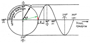
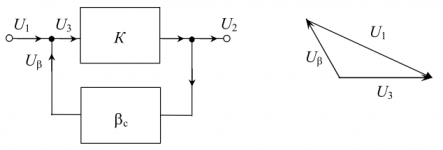
If the addition of vectors occurred according to the law of arithmetic 2 + 2 = 4, then no distortion of the output voltage would occur. It would simply be shifted by the delay time, if there were only vector distortions which, in steady state, do not affect the distortion.
But since these are vectors, as a result of the addition of vectors, distortions proportional to the delay time arise in the initial section. I hope everything is clear from the presented figures. With a delay of 1.5 μs, the real time of the introduced distortion is 2 times longer, and the amplitude reaches 5.6 Volts at a voltage of 30 Volts, which is 19% as a percentage !!!
I hope there is no need to explain that the less the signal transmission delay is, the less distortion will be introduced.
In fact, the problem is not even in the level of introduced distortion; in acoustic systems, the distortion is much higher compared to the distortion of amplifiers in the steady state. The worst thing in this business is the loss of micro-level information that makes music alive.
Imagine that a large orchestra is playing and at some moments the higher harmonics collapse and their total slew rate reaches the slew rate of the initial section of the signal shown. This harmonic, even if its amplitude reaches 6 V, will simply be smeared for up to 3 μs, ignored by the amplifier.
This is my last attempt to show what is called "on the fingers" how NFB really works in amplifiers. If this time the pundits do not understand, then I am powerless to help you with anything ... Well, whoever understands what I am talking about, he, I hope, received a useful lesson for the future "how not to do"
regards
Petr
Let's simulate an ideal transient-free follower with a signal propagation delay of 1.5 μs and see the output signal (red). The input voltage is shown with black line, blue line shows the input voltage delayed by 1.5 μs.
If the addition of vectors occurred according to the law of arithmetic 2 + 2 = 4, then no distortion of the output voltage would occur. It would simply be shifted by the delay time, if there were only vector distortions which, in steady state, do not affect the distortion.
But since these are vectors, as a result of the addition of vectors, distortions proportional to the delay time arise in the initial section. I hope everything is clear from the presented figures. With a delay of 1.5 μs, the real time of the introduced distortion is 2 times longer, and the amplitude reaches 5.6 Volts at a voltage of 30 Volts, which is 19% as a percentage !!!
I hope there is no need to explain that the less the signal transmission delay is, the less distortion will be introduced.
In fact, the problem is not even in the level of introduced distortion; in acoustic systems, the distortion is much higher compared to the distortion of amplifiers in the steady state. The worst thing in this business is the loss of micro-level information that makes music alive.
Imagine that a large orchestra is playing and at some moments the higher harmonics collapse and their total slew rate reaches the slew rate of the initial section of the signal shown. This harmonic, even if its amplitude reaches 6 V, will simply be smeared for up to 3 μs, ignored by the amplifier.
This is my last attempt to show what is called "on the fingers" how NFB really works in amplifiers. If this time the pundits do not understand, then I am powerless to help you with anything ... Well, whoever understands what I am talking about, he, I hope, received a useful lesson for the future "how not to do"
regards
Petr
Attachments
No problem with your recommendations on how to improve things. The problem lies with your use of FCD (which you do not even know how to measure nor correctly interpret) as a valid parameter to characterize quality of an amplifier.Guerilla, none of those who have approached me with a request to help cure a vintage amplifier have complained that they wasted their time on improving the amplifier according to my recommendations...
Find me a microphone that fast, let alone a commonly used audio recording media.Imagine that a large orchestra is playing and at some moments the higher harmonics collapse and their total slew rate reaches the slew rate of the initial section of the signal shown. This harmonic, even if its amplitude reaches 6 V, will simply be smeared for up to 3 μs, ignored by the amplifier.
...Imagine that a large orchestra is playing and at some moments the higher harmonics collapse and their total slew rate reaches the slew rate of the initial section of the signal shown. This harmonic, even if its amplitude reaches 6 V, will simply be smeared for up to 3 μs, ignored by the amplifier.
.....
Please just explain what happens in the next cycle. Do the implied error also occur, in the same way, here or is only within the first (360 deg) cycle?
//
Hypothetical input and output signal of a virtual amplifier. Does not sound good in a simulated listening test.
I try to "bridge" / translate between the 2 sides hopefully to come closer. 🙂
Petr:
This yellow triangle is true but they are saying that this phenomena is such an
extreme that only occurs if you feed a signal to your system that is even faster
then the open loop + FB speed of the amplifier. But if the signal max (raising)
speed is always (much) slower then this delay then this case almost never
happens and so that yellow triangle is so small that's not relevant anymore.
So it's there all the time but it's neglible.
On your image it's so big because 1.5us is a huge value + the signal speed when
starting it from 0 is so huge that the system has a section while it follows
the input signal in "open loop mode" with it's max open loop slew rate.
(But I'm not sure how it's produced on your example as it's slower then after the loop is closed.)
So the only case this could affect the audio quality would be if the
signal that builds up the final max 20kHz audio signal would need
near MHz frequency response or something like that.
But how could this happen if a CD doesn't already contain such frequencies?
Last edited:
I try to "bridge" / translate between the 2 sides hopefully to come closer. 🙂
Good luck 😉 He needs to abandon his simulated fantasy and face reality for that to happen.
Hypothetical input and output signal of a virtual amplifier. Does not sound good in a simulated listening test.
Agreed. A completely artificial construct, which has no bearing to the physical universe.
Jan
On a sinusoidal signal in a steady state (as we usually measure with Audioprecision), we will not see anything, since we measure the average distortion, say, at the 1000th and further period.Please just explain what happens in the next cycle. Do the implied error also occur, in the same way, here or is only within the first (360 deg) cycle?
//
But the music signal is not a sinusoid, it is constantly changing and OOS is constantly trying to pull up the output signal to the original with a signal propagation delay. The less this delay is, the more accurate the signal amplification will be. It was not for nothing that I brought the work of the filter on switched capacitors, which perfectly fulfills its function on stationary signals, but as soon as a multi-tone signal arrives, its work deteriorates 1000 times. So it is here.
Well, what would you expect if you make better compensation and even sometimes increase the depth of feedback? Should deterioration have occurred? ))Guerilla, none of those who have approached me with a request to help cure a vintage amplifier have complained that they wasted their time on improving the amplifier according to my recommendations. I only get thanks ... So keep your sarcasm to yourself.
Here only this initial moment of time is present only at inclusion (the beginning of the analysis) and at an overload on a differential input signal. But these are not the working modes of the amplifier and no one listens to music in them.Let's simulate an ideal transient-free follower with a signal propagation delay of 1.5 μs and see the output signal (red). The input voltage is shown with black line, blue line shows the input voltage delayed by 1.5 μs.
If the addition of vectors occurred according to the law of arithmetic 2 + 2 = 4, then no distortion of the output voltage would occur. It would simply be shifted by the delay time, if there were only vector distortions which, in steady state, do not affect the distortion.
But since these are vectors, as a result of the addition of vectors, distortions proportional to the delay time arise in the initial section. I hope everything is clear from the presented figures. With a delay of 1.5 μs, the real time of the introduced distortion is 2 times longer, and the amplitude reaches 5.6 Volts at a voltage of 30 Volts, which is 19% as a percentage !!!
The worst thing about this is listening to music in the simulator without being able to actually listen to your circuits. And to judge the quality of sound only by the reviews of other people, then leaning on this shaky ground if necessary argumentation. It won't go through any gates.I hope there is no need to explain that the less the signal transmission delay is, the less distortion will be introduced... The worst thing in this business is the loss of micro-level information that makes music alive.
Instead of modulating the sine with a rectangular signal, as you do when applying a sinusoidal burst, apply a signal of 19kHz and 20kHz - here's the modulation with a normal signal. The amplitude changes, everything is within the bounds of decency. What's not to like? Why is it necessary to manually overload the comparison point?Imagine that a large orchestra is playing and at some moments the higher harmonics collapse and their total slew rate reaches the slew rate of the initial section of the signal shown. This harmonic, even if its amplitude reaches 6 V, will simply be smeared for up to 3 μs, ignored by the amplifier.
As a hard test in the simulator, you can raise the bar, if you really want to and submit for example 24kHz+25kHz. At the same time, at a sufficient slew rate, the amplifier will draw the difference signal with a smooth sine, ideally, if you have an output stage that does not produce switching distortions.
In fact, your conclusions about the summation of the harmonics of the orchestra have no basis, except for speculative ones. Use the math to prove it.
For my part, I will say that it is enough to take the maximum amplitude and frequency at the amplifier output in order to calculate the required SR at the output. Then divide by the amplifier gain and bring this parameter to the input. This will be an indicative SR input level.
Take 20kHz and 40V and SR = 5V / us, divide by 15 for about 2.82V input amplitude and get 0.34 V / us.
Let's compare with the results of Peter Baxandall. I don't remember exactly, but he seems to be giving something like 0.5 V / us as the maximum value he found. So now give your calculations as a counterargument.
On the other hand, if we sum up the slew rates of even two signals at the input (or output, without a difference), we must understand that we cannot simply take and add the maximum slew rates, since then this is adequate for exceeding the permissible output amplitude and the clip.
Example for 40V output amplitude acceptable. We summarize 20V at 20kHz and 20V at 5kHz (SR is 2.512 V / us and 0.628V / us, respectively) and in total is 3.14 V / us. As you can see, this is less than the above calculation for a single frequency of 20kHz and 40V. And so it will always be, until you enter the clip, exceeding 40V output voltage.
Don't bend your fingers, you better learn your lesson today.This is my last attempt to show what is called "on the fingers" how NFB really works in amplifiers. If this time the pundits do not understand, then I am powerless to help you with anything ... Well, whoever understands what I am talking about, he, I hope, received a useful lesson for the future "how not to do"

Last edited:
- Home
- Amplifiers
- Solid State
- First cycle distortion - Graham, what is that?