^^^
All correct, but you did not quote anything in your post #761, so I was assuming you are addressing the post #760 above, from fagos, which was not about this large signal slew rate mechanism, but about his #754. Sorry for the confusion.
No appoligy needed, I know were on the same page. Just trying to add some info for those that dont know about LTP overload.
(Wow you guys are amazing... 😀
And maybe a little bit (too) eager to judge...
But I guess it's such a good feeling to push somebody down so I forgive and simply ignore it. 🙂
BTW I didn't ask this because I don't know how harmonics are generated.)
Thanks Jan for your example and image! But let's just move on.
So my next question what other sources can you say what also can produce
harmonics except the "stateless" non linear gain of a device?
As I said. Amazing.
Jan
Jan, you show the patience of a Buddhist monk and in return you get abuse. Keep it up and youll atain Sainthood (or go crazy). The Saint of Diyaudio.
Last edited:
And then as the distortions begin to circulate in a circle in the NFB circuit... What are we going to do about it then?😀
No,no, Jan will have kittens 😉
I see we’re still flogging that dead horse? Best wishes for 2021 gents, may you find lots of enjoyment listening to music and tinkering with audio electronics!
No,no, Jan will have kittens 😉
Maybe it is time for full disclosure. Feedback cannot work because you cannot correct something that has already happened.
And don't come to me with air planes that don't fall out of the sky because they are controlled by feedback systems - it's a hoax! There ARE NO airplanes, all fake news!
And those nuclear power plants that are kept in check (mostly) with feedback control systems - a hoax! they are just painted over coal fired plants! Oh wait, those coal fired plants are kept non-exploding with feedback control systems - a hoax! They are just a huge bunch of batteries painted over as coal fired plants! We're all taken in by the feedback hoax!
And don't let anybody tell you that human breathing is regulated by feedback control from the CO2 blood level - humans don't really breath, they are just going through the motions. A hoax, all of it, I tell you!
Happy New Year, wishing you a year where Corona is just a beer brand, and Donald is just the name of a duck ;-)
Jan

Happy New Year, wishing you a year where Corona is just a beer brand, and Donald is just the name of a duck ;-)
Unfortunately there's another duck AKA Boris.
Happy New Year, wishing you a year where Corona is just a beer brand, and Donald is just the name of a duck ;-)
Jan
Happy new year Jan, Ovidiu, Damir and everybody else.
Lets hope that in 2021 we get rid off Corona and Donald(not the duck) the golfplayer.
Best wishes
Stein
Last edited:
It seems the intent of imposing a "first cycle” (or alternative stimulus) is to obtain incite into an analysis of the resulting output waveforms having correlation to some psychoacoustic phenomenon. Yet this seems an obscure means to comprehend what can be more easily and universally understood in considering amplitude modulation (“AM”) detection phenomenon.
A sign of the prevalence of this phenomenon is to conduct two stimulus tests with two different frequencies (say 1KHz and 2KHz. If both rise or fall (as shown in some previous posts) with the same RC time constant its the product of a modulation phenomenon. A more advanced means is to create a stimulus that modulates the carrier (perhaps 1KHz) at a 100Hz rate and observe if a 100Hz signal appears in the spectrum.
A sign of the prevalence of this phenomenon is to conduct two stimulus tests with two different frequencies (say 1KHz and 2KHz. If both rise or fall (as shown in some previous posts) with the same RC time constant its the product of a modulation phenomenon. A more advanced means is to create a stimulus that modulates the carrier (perhaps 1KHz) at a 100Hz rate and observe if a 100Hz signal appears in the spectrum.
Once upon a time I needed a high-quality notch filter with high temperature stabilization. It would seem that it is easier, you take a circuit on switched capacitors and get the result. Indeed, the filter turned out to be simple and high-quality, suppression of the fundamental frequency was about 85 dB. But this is only on stationary sinusoidal signals, well, as well as measuring distortion in audio frequency amplifiers in a steady state. As soon as a multi-tone signal was applied, including a rejection signal, only 25 dB or even less remained from 85 dB of suppression (1000 times worse!).
Who knows what such a filter is, he knows that its work is based on RC-chains of the first order, a kind of integrators. In this thread, many colleagues also compare the work of NFB with the work of an RC chain (the same fagos). The operation of amplifiers with NFB is similar to the operation of a notch filter.
Yes, indeed, everything works fine on a stationary signal. But as soon as a complex signal arrives, other than a sinusoidal one, the work of such a system falls apart, since it takes time to complete the establishment processes. Yes, it somehow works, but the auditory system cannot be fooled.
It goes without saying that the shorter the signal propagation delay time, the less the first period distortion (FCD). It has been practically and theoretically proven that tPD should be no more than 50 ... 70 ns, well, a maximum of 100 ns so that this delay does not have a noticeable effect on the operation of the NFB.
Once you understand this, you will finally understand why there is no correlation of sound quality with such a parameter as THD.
Last edited:
I think everybody here understand both multi tone and propagation delay, no problem. There are established standard in doing the tests.
Nobody else here but you feel the need to add FCD into the multitude of standard tests already available. FCD does not bring new understanding, only add complication and potential abuse by snake oil peddlers.
Nobody else here but you feel the need to add FCD into the multitude of standard tests already available. FCD does not bring new understanding, only add complication and potential abuse by snake oil peddlers.
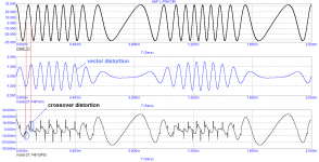
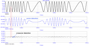
The quiescent current of both amplifiers is the same - 116 mA each
Experience the Difference Between Two Amplifiers
The first amplifier has much larger vector distortions, since the signal propagation delay time is longer.
The first amplifier also copes worse with switching distortion due to the slow NFB.
measurements carried out by the Baksandall method
Experience the Difference Between Two Amplifiers
The first amplifier has much larger vector distortions, since the signal propagation delay time is longer.
The first amplifier also copes worse with switching distortion due to the slow NFB.
measurements carried out by the Baksandall method
Attachments
Last edited:
Both vector and crossover distortion is enough to show amp 2 is better than amp 1. Why do you need another distortion test procedure such as FCD to show the already obvious difference?
Last edited:
I use the test in the first period only as an express analysis, nothing more.Both vector and crossover distortion is enough to show amp 2 is better than amp 1. Why do you need another distortion test procedure such as FCD to show the already obvious difference?
If you've read my amplifier testing reviews, they include over ten different tests. Not every review has all of them, of course.
strictly speaking, having some experience, you can predict the behavior of the amplifier by looking at the group delay
Last edited:
Do you understand that you need a 24 / 32 bit ADC operating at a few MHz to make reasonably accurate measurement of a first cycle 1 khz signal? Let us see how you implement measurement for the express analysis.
measurements are made virtually, and Graham has repeatedly written about this. If we are interested in what is happening in the first period, then we can see it visually using the transient analysis. I am delighted with the book by Jiri Dostal where he described in detail the distortions arising in the amplifiers.
all measuring devices contain filters whose settling time is rather long. Therefore, their readings are averaged, like the average temperature of patients in the hospital: 39 degrees in patients, and 33 degrees in a morgue, an average of 36 degrees (conditionally)
all measuring devices contain filters whose settling time is rather long. Therefore, their readings are averaged, like the average temperature of patients in the hospital: 39 degrees in patients, and 33 degrees in a morgue, an average of 36 degrees (conditionally)
Last edited:
- Home
- Amplifiers
- Solid State
- First cycle distortion - Graham, what is that?