Another question I'm curious to the answers about:
How a 1kHz input signal can (even continuously) produce a higher frequency harmonics, "signals"?
It is not the input signal that produces the harmonics. It's the amp.
Send a sine wave through a circuit that has a quadratic transfer function. What do you get at the output?
Say your amp has a transfer function (gain): Vo = (30 x Vi) + (0.1 x (Vi^2).
Now send in a 1V 1kHz signal: Vi = sin((1k/2*pi)*t). What is the output?
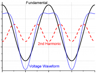
There is also an intuitive way to understand. Say your amp distorts, literally, your input sine wave. Maybe on the output the pos. part is a bit less in amplitude than the negative part (blue dotted wave). What is the shape difference between the input (black trace) and this distorted output? Fourier tells us the output is made up of the original summed with another wave that decreases the pos. part and increases the neg. part. Lo and behold, the 2nd harmonic (dotted red trace) fulfills that role!
Jan
Attachments
Last edited:
I find it curious how someone can dream up grand theories about FCD without even understanding what distortion is and how it is created.
Let alone the intricacies of settling time and such. Amazing.
Maybe I am too old to understand such a mindset.
Jan
Let alone the intricacies of settling time and such. Amazing.
Maybe I am too old to understand such a mindset.
Jan
Amazing indeed.
Think what will happen with "analog" knowledge in 50 years... it will be like magic for most.
//
Think what will happen with "analog" knowledge in 50 years... it will be like magic for most.
//
Regarding noise floor modulation, please see specifications section on page 2 of the datasheet at:
Overview | CSRA6620 | Qualcomm
Or, how about Texas Instruments, page 6: https://www.ti.com/lit/an/slaa114/s...74146&ref_url=https%3A%2F%2Fwww.google.com%2F
Comments:
I will admit it is specialist terminology. Bruno Putzeys described more or less the same measurement symptom caused by idle tones sweeping through the audio band caused by the audio signal, which is seen a modulation of the noise floor correlated with the audio. (My note: the measurement appears that way exactly because the because the underlying cause is not stationary relative the the FFT measurement time frame.)
Its also seen in the widely cited patent at:
GB2539517A - Systems and methods for reducing artifacts and improving performance of a multi-path analog-to-digital converter
- Google Patents
Also, described in an EE class (page 59):
http://cloudportal.sathyabama.ac.in/coursematerial_staging/uploads/SEC1319.pdf
In the AES document, "Why 1-Bit Sigma-Delta Conversion is Unsuitable for High-Quality Applications."
Lipshitz and Vanderkooy state (page 4): "...display gross modulation of the noise floor in the audio band"
https://timbreluces.com/assets/sacd.pdf
Last edited:
Jan
I just want to set the record straight after some of accusations and attacks that were made in this thread. I will be happy to let it go now.
I just want to set the record straight after some of accusations and attacks that were made in this thread. I will be happy to let it go now.
(Wow you guys are amazing... 😀
And maybe a little bit (too) eager to judge...
But I guess it's such a good feeling to push somebody down so I forgive and simply ignore it. 🙂
BTW I didn't ask this because I don't know how harmonics are generated.)
Thanks Jan for your example and image! But let's just move on.
So my next question what other sources can you say what also can produce
harmonics except the "stateless" non linear gain of a device?
(Wow you guys are amazing... 😀
And maybe a little bit (too) eager to judge...
Not really. Have you understood yet how distortion in a first cycle, even if it was caused, is utterly meaningless?
If you want to see how the amplifier comes out of overload, then why do you need to come up with something exquisite, if there is a regular test with a rectangular signal? Why give a step in the composition of the burst in a veiled way, if you can do it openly and get a more convenient result for visual evaluation? I sincerely do not understand why I have to come up with methods to scratch my nose with my heel, if it is more convenient with my hand.Then can you please provide an old and proven method which analyzes specifically the
very first time section of output response after a signal is applied to the input?
You have little idea of the processes that occur in an amplifier with NFB, so you are easily confused by the results of Petrov's simulations. With the proper level of knowledge in the head should already have a filter that protects against delusional ideas. I have shown enough in my posts throughout the topic to separate the wheat from the chaff. And other participants in the discussion showed even more and more versatile. When the sine is applied, there is no sharp start (there is no hidden modulating step) and the amplifier manages to work out the input signal rise without increasing the differential voltage at its inputs. As soon as we apply a step - there is a lag of the output signal from the input and the differential voltage between the inputs of the comparison node increases.I guess you were saying frequency and phase response but again: and please correct me if
I'm wong but these measurements are also taking place after some delay and not "real time"
so they are not telling anything about the transient (very first time section) respose
just an average transfer in the "AC domain" which means they can transfer/amplify a
given frequency on a continuous sine wave with a given gain and phase on average.
I'm not saying it has no correlation with the transient response at all just mention the
possibility that it could miss some "glitches" at the very beginning of the process when
the system is changing state.
You have little idea of the processes that occur in an amplifier with NFB, so you are easily confused by the results of Petrov's simulations. With the proper level of knowledge in the head should already have a filter that protects against delusional ideas. I have shown enough in my posts throughout the topic to separate the wheat from the chaff. And other participants in the discussion showed even more and more versatile. When the sine is applied, there is no sharp start (there is no hidden modulating step) and the amplifier manages to work out the input signal rise without increasing the differential voltage at its inputs. As soon as we apply a step - there is a lag of the output signal from the input and the differential voltage between the inputs of the comparison node increases.
I showed you how the amplifier responds to a sine with a step here
https://www.diyaudio.com/forums/att...89d1608660303-cycle-distortion-graham-288-png
Let me explain - you see a "floating" sine at the output, which consists of the sine itself and the hump of the transition process caused by the step
If you look at Petrov's graphs and see sharp peaks of distortion as a result of the influence of the sine, you should have a natural question - what causes it and what is the mechanism. These are the right questions. A sharp peak can only give the same sharp impact on the input. If you don't see it, it's veiled by the signal it modulates. But it is there!
https://www.diyaudio.com/forums/att...n-graham-composit_vs_lpf_speed_distortion-png
Here you see Petrov laid out a graph with different sinuses, but there are gaps between them, which are step effects and it is at these moments that distortion peaks appear as if by magic. And since the simulator calculates everything step by step, there is always a transition if the source is glued together from pieces. Don't you believe it? Apply the sum of 19kHz and 20kHz and you will not see such peaks in the signal between the outputs, although the signal jumps up and down at almost the maximum speed for the audio range.
And in addition... It amuses me when a person like Petrov talks about the bad sound of amplifiers that he has not collected or heard in his life. This is at least false information, which has a desire to support its arguments with pseudo-facts. That is why I have long ceased to believe his words and ask for links to primary sources and mathematical calculations that you can check and read yourself.
You got that right. Since I and many others here are not, hopefully if you are interested enough to obtain measurement you will finally gain the proper understanding of the matter.... No one said it can't be measured somehow if we are intrested...
Regarding noise floor modulation, please see specifications section on page 2 of the datasheet at:
Overview | CSRA6620 | Qualcomm
Or, how about Texas Instruments, page 6: https://www.ti.com/lit/an/slaa114/s...74146&ref_url=https%3A%2F%2Fwww.google.com%2F
Comments:
I will admit it is specialist terminology. Bruno Putzeys described more or less the same measurement symptom caused by idle tones sweeping through the audio band caused by the audio signal, which is seen a modulation of the noise floor correlated with the audio. (My note: the measurement appears that way exactly because the because the underlying cause is not stationary relative the the FFT measurement time frame.)
Its also seen in the widely cited patent at:
GB2539517A - Systems and methods for reducing artifacts and improving performance of a multi-path analog-to-digital converter
- Google Patents
Also, described in an EE class (page 59):
http://cloudportal.sathyabama.ac.in/coursematerial_staging/uploads/SEC1319.pdf
In the AES document, "Why 1-Bit Sigma-Delta Conversion is Unsuitable for High-Quality Applications."
Lipshitz and Vanderkooy state (page 4): "...display gross modulation of the noise floor in the audio band"
https://timbreluces.com/assets/sacd.pdf
Sorry, frantically searching Google for a string also doesn't cut it. The Qualcomm product overview (which is anything but a technical description, and to add insult to injury is about Class D amplifiers) doesn't explain anything and qualifies as a marketing material. I can only wildly assume it is about overloading effects, which, as I mentioned in my original question, do create a noise floor "grass" due to the harmonic components resulting for intermodulation. The rest of quotes also don't explain a iota of your understanding of the "noise floor modulation" concept. If you would read my original question carefully, you would for sure realize that it is not the concept of "noise floor modulation" that was under question, but your use (and abuse) in the noted context. It is funny that the TI white paper you quoted above, and the EE class material you quoted next, illustrate exactly what I have mentioned:
I know a spectrum analyzer noise floor can be "modulated", if the instrument has not enough dynamic range for the measurement, I know the noise floor can be in general modulated by a carrier single frequency, but I have no idea how to modulate the noise floor with a random (music) signal, of course without running the system into non linearities (like for example clipping).
These are well known effects and nobody debated them.
L & V AES paper has nothing to do with "noise floor modulation" but only sets the foundation for an ultra known fact, that an 1-bit modulator has limitations (and that's why the ESS DAC, for example, is using a 6-bit modulator, no idea about the AKM devices).
About your own comment, there is only one qualifier: doesn't compile whatever way or direction it is read. Name dropping (Bruno Putzey) is not helping.
If you want to have an educated discussion about DAC limitations, we can do so, in another thread. But the pre-requisite is to set aside any techno babble, use a language that belongs to the EE body of knowledge, and refrain from using subjective BS, abusing known facts, name dropping, and unsubstantiated claims.
Last edited:
Or, he could save a lot of time and do dadod's listening testYou got that right. Since I and many others here are not, hopefully if you are interested enough to obtain measurement you will finally gain the proper understanding of the matter.
And then as the distortions begin to circulate in a circle in the NFB circuit... What are we going to do about it then?😀Or, he could save a lot of time and do dadod's listening test
...But the pre-requisite is to set aside any techno babble, use a language that belongs to the EE body of knowledge, and refrain from using subjective BS, abusing known facts, name dropping, and unsubstantiated claims.
Hurray 🙂
HNY!!
//
I wasn't saying overload testing. And neither a response to a step signal.If you want to see how the amplifier comes out of overload, then why do you need to come up with something exquisite
But your (russian? labeld) figure shows that the response has a decaying settlement section at the beginning.
And if this settling response to a (not infineitely) fast signal shows different behaviour
between 2 amps then why we couldn't use this method to get some additional info..?
And as I said earlier (for me) 2 main interpretations can be made about FCD:
a) the step signal response -> here the input signal is a suddenly starting sine wave
I leave this FCD type on Petr as I'm more intrested on option "b)"
b) settlement response -> here the step test signal is not a must at all
and a "slowly" staring sine wave is perfect (but under slowly I mean a few periods not 100).
And then we check the response for the very first complete (100% normal amplitude) sine wave at the output.
And then we compare this result with the 10th, 30th, ..., 100th periods as well.
If the 1st (few) one has a much higher distortion then the later ones, the system has a decaying distortion profile.
And if an "A" amplifier differs in this aspect from amp "B" then we
could say that it's "faster" even if they have the same bandwidth.
And after that we could check the correlation with the final sound quality as well.
But maybe this b) option is just my false interpretation of FCD and I shouldn't hijack this topic with it at all... 🙄
If you mean in #754, then no, that's not slew rate, not even remotely. There's nothing that can run into nonlinearities, like saturating/blocking the input stage in a LTP. That's rise time, or, if you prefer, the effect of finite bandwidth in a first order system response.
Isnt that what were talking about. A square wave or any signal that has fast risetimes like pulsed sines as a test signal? This whole first cycle nonsense.
Just as explanation of what I meant: If I hit an LTP (with no LPF at input) with a fast 1v square the + side goes to 1V while the - side is still at zero. This drives the LTP (which only sees milivolts across +/- in normal operation) into saturation, non linear region. I am asuming a reasonable amount of feedback in the design.
Last edited:
^^^
All correct, but you did not quote anything in your post #761, so I was assuming you are addressing the post #760 above, from fagos, which was not about this large signal slew rate mechanism, but about his #754. Sorry for the confusion.
All correct, but you did not quote anything in your post #761, so I was assuming you are addressing the post #760 above, from fagos, which was not about this large signal slew rate mechanism, but about his #754. Sorry for the confusion.
Last edited:
- Home
- Amplifiers
- Solid State
- First cycle distortion - Graham, what is that?