What you are testing is slew rate, thats all, nothing new. Any transient input to amps thats fast enough, like your stepped sine will cause slewing. Which is like clipping, it takes the amp out of its linear region. Different topologies deal with slewing differently, thats all your showing and like clipping it has nothing to do with the amps performance in its linear region. So you waste your time finding a solution to a problem that dosnt exist.
Theres a definite lack of signal theory understanding in this discussion when people deny the BW of stepped signals. AND never does a band limited signal have a transient faster than its highest freq. Anyone who denies this is beyond discussion.
Theres a definite lack of signal theory understanding in this discussion when people deny the BW of stepped signals. AND never does a band limited signal have a transient faster than its highest freq. Anyone who denies this is beyond discussion.
For anyone interested, noise floor modulation in dacs as explained by Martin Mallison:
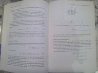
"...in a quiet passage of music the state variables of the modulator are all operating within a certain “state space” and the quantization noise shaping is described by the noise characteristics in this “volume” of the space. After a large music transient has passed, the output traces its dynamic response back to the quiescent operating point as we expect, but every state variable is also following its transient response back to its quiescent point. (The operating point in the machine state space is returning to the
quiescent position – all the dimensions of the state are changing.) During this multi-dimensional excursion back to the lower signal level the operating point traverses different volumes of the space, each of which has its own noise characteristic. Hence a very perceptive listener can hear something “anomalous” related to the transient response."
http://www.esstech.com/files/4314/4095/4318/sabrewp.pdf
My own opinion:
Understanding the above may lead to test for potential preamp power cord audibility by applying broadband RF noise to at the power connector and observing the noise floor of the preamp changing in a way that is correlated with audio signal characteristics. If the effect is caused by RF, the removing the RF at the power connector should cause the noise floor modulation to cease or at least be significantly attenuated.
An RF filter at the preamp power entry point could be fitted and it effect on noise floor modulation measured.
Eventually listening tests sans power entry filter would need to occur to show there can be an audible effect correlated with measured environmental RF. Then a filter could be fitted and listening tests repeated to show the effects of the filter in terms of audibility.
IIUC, design of Monster HTPS 7000 Mk II involved similar environmental noise measurements, along with listening tests. Again IIUC, it was proprietary research, not for public disclosure.
Last edited:
No.
Its only to help with understanding what noise floor modulation is, that is correlated with the audio signal, that it can be measured, and that it can be audible. That's the reason for mentioning the dac paper.
Its only to help with understanding what noise floor modulation is, that is correlated with the audio signal, that it can be measured, and that it can be audible. That's the reason for mentioning the dac paper.
For anyone interested, noise floor modulation in dacs as explained by Martin Mallison:
Does he give any example of the size of transient required to give this and the dynamic range differences we are talking about? Or even any available music that would show this effect or is this a beard twiddling hypothesis?
I don't see the correlation with DSP settling to a new state . Also do not understand the part marked in bold.Understanding the above may lead to test for potential preamp power cord audibility by applying broadband RF noise to at the power connector and observing the noise floor of the preamp changing in a way that is correlated with audio signal characteristics.
IIUC, design of Monster HTPS 7000 Mk II involved similar environmental noise measurements, along with listening tests. Again IIUC, it was proprietary research, not for public disclosure.
The giggle of course being that one of the people involved in said hunk of iron (RNM) failed to see the irony of using power line ethernet adaptors in his listening room.
What you are testing is slew rate, thats all, nothing new.
If you mean in #754, then no, that's not slew rate, not even remotely. There's nothing that can run into nonlinearities, like saturating/blocking the input stage in a LTP. That's rise time, or, if you prefer, the effect of finite bandwidth in a first order system response.
Last edited:
For anyone interested, noise floor modulation in dacs as explained by Martin Mallison:
"...in a quiet passage of music the state variables of the modulator are all operating within a certain “state space” and the quantization noise shaping is described by the noise characteristics in this “volume” of the space. After a large music transient has passed, the output traces its dynamic response back to the quiescent operating point as we expect, but every state variable is also following its transient response back to its quiescent point. (The operating point in the machine state space is returning to the
quiescent position – all the dimensions of the state are changing.) During this multi-dimensional excursion back to the lower signal level the operating point traverses different volumes of the space, each of which has its own noise characteristic. Hence a very perceptive listener can hear something “anomalous” related to the transient response."
http://www.esstech.com/files/4314/4095/4318/sabrewp.pdf
My own opinion:
Understanding the above may lead to test for potential preamp power cord audibility by applying broadband RF noise to at the power connector and observing the noise floor of the preamp changing in a way that is correlated with audio signal characteristics. If the effect is caused by RF, the removing the RF at the power connector should cause the noise floor modulation to cease or at least be significantly attenuated.
An RF filter at the preamp power entry point could be fitted and it effect on noise floor modulation measured.
Eventually listening tests sans power entry filter would need to occur to show there can be an audible effect correlated with measured environmental RF. Then a filter could be fitted and listening tests repeated to show the effects of the filter in terms of audibility.
IIUC, design of Monster HTPS 7000 Mk II involved similar environmental noise measurements, along with listening tests. Again IIUC, it was proprietary research, not for public disclosure.
Doesn't qualify, not even as a nice try. The concept of "noise floor modulation" appears nowhere in the ESS white paper. What you quoted does not mention anything like "noise floor modulation". Mind you, the DAC modulator and "noise floor modulation" have nothing in common. The transient response of the modulator has also nothing to do with "noise floor modulation" so I must assume you have no idea what that is. Admittedly, neither do I 😀, only that I refrain from using BS concepts.
BTW, there's nothing outstanding required to understand the ESS white paper (which has several questionable assumptions and conclusions, but this is already off topic) other than a minimum of knowledge in signal processing, true, over the head of the average DIYer. In my book, promoting such undigested information for the purpose of appearing knowledgeable is a dishonest procedure, it's like I would want to be appreciated as a theoretical physicist after trying to explain quantum physics to my church congregation.
Your opinion has nothing to do with the topic, it's just another smoke screen trying to obfuscate the discussion and promote your subjective, super natural hearing, agenda.
Last edited:
I decided to skim the ESS advertorial. I note that topping and tailing the quote Mark used is
Shame as this falls into the 'find a FUD and fix it' approach of high end audio marketing. I am sure the Engineers at ESS DID work hard to prevent this, but that was lost on this whitepaper.
Of course no names and no measurements of this.Secondly, certain ΣΔ modulators when provided with a rapidly changing input signal will exhibit non-linear noise behavior as they process the transien
We have designed our HyperStream modulators to exhibit strongly damped responses in all state variables. This means that a low level signal processed just prior to a transient and just after a transient, is processed in the same corner of the state space of the modulator and hence in the same quantization noise environment, thereby eliminating the anomalous errors in the music reproduction.
Shame as this falls into the 'find a FUD and fix it' approach of high end audio marketing. I am sure the Engineers at ESS DID work hard to prevent this, but that was lost on this whitepaper.
From the point of view of psychoacoustics, the first 18 harmonics are responsible for the timbre of the sound and its natural sound. Of these, the most important are the first 8 harmonics, and each of them must be strictly in its place.
The treble of sonic instruments is about 5 kHz, multiply by 18 to get 90 kHz. It was with such a bandwidth that reference acoustics began to be made.
But even if we close our eyes to the last harmonics and leave only 8, then the bandwidth of the recorded signal should be at least 40 kHz, which is not actually in the SD format. Nevertheless, even with the castrated signal that we have different amplifiers sound differently and it does not depend on the number of zeros after the decimal point in the steady state.
The acoustics itself introduces several percents and we do not hear them, nevertheless we hear the difference in the sound of different amplifiers and, as Graham wrote, it depends on the amplifier's ability to correctly amplify the signal starting from the first period.
Graham repeatedly drew attention to the fact that amplifiers that are not able to qualitatively amplify the signal from the first period have an unstable group delay, which leads to phase shifts of the high-frequency components of the signal that are responsible for the sound timbre.
From myself, I can add that in amplifiers with a signal propagation delay higher than 70 ... 100 ns, thin low-level information of the sound material is lost and the sound becomes dead, boring.
I specifically took a composite amplifier for an example, which in the steady-state mode has distortion with ten zeros after the decimal point, and in the first period, the distortion is 0.8%. At the same time, the JLH-69 amplifier introduces distortion in the first period of 0.04%, and the Graham GEM amplifier - only 0.003%. In subsequent periods, these figures decrease slightly.
Most of those participating in the discussion do not want to understand in any way what the essential difference is between amplifiers that introduce distortion in the first period and those amplifiers that do not introduce these distortions.
Jan, of all amplifiers, the Denon PMA-530 and JVC A-X5 have the greatest RIMD distortion, and both of them have tone controls in NFB. Moreover, in the PMA-530 amplifier at the output of the Darlington "two" at the inputs of which there are 1 kOhm resistors, and in the bases of the output transistors of 47 Ohm, which is a lot. Even without simulation, it is clear that the group delay of these amplifiers will be much more than 100 ns.
Colleagues often ask me for advice on how to upgrade vintage amplifiers. As soon as I see the tone control in NFB, I immediately remove it and then optimize to reduce the signal propagation delay time as much as possible.
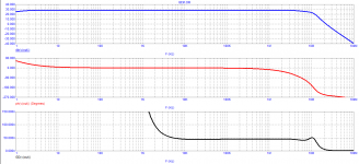
By the way, here is the Bode diagram of the Graham amplifier, the GD is measured with a "caliper" (according to the expression of the fagos). Group delay less than 50 ns and constant in the band up to several MHz. The JLH-69 amplifier has a slightly higher delay (about 80 ns) and is stable up to 500 kHz.
Colleagues often ask me for advice on how to upgrade vintage amplifiers. As soon as I see the tone control in NFB, I immediately remove it and then optimize to reduce the signal propagation delay time as much as possible.
By the way, here is the Bode diagram of the Graham amplifier, the GD is measured with a "caliper" (according to the expression of the fagos). Group delay less than 50 ns and constant in the band up to several MHz. The JLH-69 amplifier has a slightly higher delay (about 80 ns) and is stable up to 500 kHz.
Attachments
There is no amplifier that does not introduce distortion, some less and others more. We understand that you are giving an opinion in which you have no measurement nor supporting math.... those amplifiers that do not introduce these distortions.
Jan, of all amplifiers, the Denon PMA-530 and JVC A-X5 have the greatest RIMD distortion, and both of them have tone controls in NFB. Moreover, in the PMA-530 amplifier at the output of the Darlington "two" at the inputs of which there are 1 kOhm resistors, and in the bases of the output transistors of 47 Ohm, which is a lot. Even without simulation, it is clear that the group delay of these amplifiers will be much more than 100 ns.
Colleagues often ask me for advice on how to upgrade vintage amplifiers. As soon as I see the tone control in NFB, I immediately remove it and then optimize to reduce the signal propagation delay time as much as possible.
By the way, here is the Bode diagram of the Graham amplifier, the GD is measured with a "caliper" (according to the expression of the fagos). Group delay less than 50 ns and constant in the band up to several MHz. The JLH-69 amplifier has a slightly higher delay (about 80 ns) and is stable up to 500 kHz.
Look at the frequency where the phase reaches -180 degrees and the corresponding point on the gain plot. 180 degrees is where nfb becomes pfb with a magnitude of around 20dB. The function of the circuit is thus converted to an oscillator.
Then can you please provide an old and proven method which analyzes specifically theDistortions have long been classified and it is quite difficult to come up with something new.
very first time section of output response after a signal is applied to the input?
Why? If for example even an abnormal/unreal/non-musical square wave test can show someit is silly to try to evaluate the sound quality by testing on out-of-band input signals
extra artifact and let's say it sometimes correlate with the final quality then why
we should't use a such a signal to test an amplifier..? The same question is for a
step signal. I still see it as just an extra drive that could bring up some
extra aspect of analyzing the behaviour even if it's a non-normal condition... Why not..?!
I guess you were saying frequency and phase response but again: and please correct me ifIt is for this reason that I do not even try to evaluate the FCD with any tool at all,
except for evaluating the frequency response and frequency response,
since this is enough to have an idea of the capabilities of the amplifier.
I'm wong but these measurements are also taking place after some delay and not "real time"
so they are not telling anything about the transient (very first time section) respose
just an average transfer in the "AC domain" which means they can transfer/amplify a
given frequency on a continuous sine wave with a given gain and phase on average.
I'm not saying it has no correlation with the transient response at all just mention the
possibility that it could miss some "glitches" at the very beginning of the process when
the system is changing state.
I guess this claim could be the "common ground" the only difference that the "believer" sideDo we need to amplify what's left out if it doesn't fit our ears? Of course, we need some margin ...
is fanatic regarding this margin and the skeptics are satisfied with a convetional margin.
But if that's the case why to argue the importance of this quantity of margin?
If someone wants to increase as much as possible why to fight against it?
Of course I can accept if someone is not intrested but I can't accept that we
all also should surrend and throw out even the possibility that can count a lot.
Maybe yes! 🙂What would be the mechanism? Amplifier surprise?
But I guess these mechanisms can be of course multiple types at the same time.
Likely mainly capacitive, inductive (inside the amplifier | built up from the layout |
coming from the PS or from the cooperation with a reactive load specially when using
feedback) and maybe even some thermal transients which are all just settling after a
time but until then they cause some extra noise, "glitches", modulation, etc.
I would call them FDD -> Fast Disappearing Distortions if you like... 😀
How a classical bode and FFT would deal with such phenomenas?
I can accept you don't belive in such things but please just for the sake of "the game"
if there would be such effects how would you try to catch/measure/display them?
And I guess the speed is important because of that and not because of the input signal transfer.
I imagine it similar to the decaying oscillation on a square wave when applying a capacitive load as well.
This layout produces an extra artifact and a settling process even if at normal conditions
it has the speed to transfer the basic signal spectrum.
But please do not start to explain that this can be seen also on a bode as the
capactive load changes the whole phase response, etc as this is now just example now.
My assumption is that similar things can happen which are only there at the very
beginning of the state changes. Of course they are much smaller (maybe faster as well)
and are disappearing after a few "periods".
I know these sentences are sounding maybe "fuzzy" but I like the approach as this also allowsDuring this multi-dimensional excursion back to the lower signal level the operating point
traverses different volumes of the space, each of which has its own noise characteristic.
Hence a very perceptive listener can hear something “anomalous” related to the transient response."
some transient state change "model" which can affect/modulate the final signal processing.
Because analyzing anything that nobody knows how to measure is absurd.... The same question is for a
step signal. I still see it as just an extra drive that could bring up some extra aspect of analyzing the behaviour even if it's a non-normal condition... Why not..?! ...
Apply an input signal from t=0 to t=x and check the output response from t=0 to t=x+y.What do you mean by "real time"?
So the point is that:
a) we don't wait while the response settles as that behaviour is exactly what's crucial for this kind of test
b) we don't average the signal but take/test it as a "frame by frame" snapshot
And "y" is a time window to check the decay section at the output after the signal already ceased at the input.
But that's only the current state. No one said it can't be measured somehow if we are intrested.Because analyzing anything that nobody knows how to measure is absurd.
Another question I'm curious to the answers about:
How a 1kHz input signal can (even continuously) produce a higher frequency harmonics, "signals"?
Can someone give a concrete practical example how it's produced?
For example taking a specific part/circuit in transient mode explaining it during a few period of the sine wave?
- Home
- Amplifiers
- Solid State
- First cycle distortion - Graham, what is that?