I think it could, but this also is just an assumption of course. My guess is that when there is a bigger and faster change there could be more transient artifacts / side effects produced as the system "slips" a little bit.
That is, again, the misunderstanding. In a bandwidth limited input signal, that is not possible. There are no 'bigger and faster' changes. This is the basic point that has to be understood, otherwise no way to communicate at the same understanding.
And it is not 'just an assumption', I don't deal in just assumptions, please don't insult me.
If I assume something, I will say so. This is factual, borne out by decades of research. This is something you should assimilate to go forward in this.
Jan
When driving it with a higher level of signal the whole system should be "warmed up" while the signal is going on/further.
That's why I like the FCD as it (maybe) can also cover this effect while a continuous sine based test can't.
Serious? A continuous sine wave has to start somewhere too, right? The system starts to warm up from the moment it is switched on and gets signal. Why would it warm up differently when it starts with a step sine rather than a 20kHz bounded sine? This defies physics.
Jan
You may be right, I'm out of my depth here. But as it is a sort of multiplication of a unit step with a sine wave, maybe we see sine wave harmonics. I don't know, hence my question.
Jan
Wouldn't the fact that it's a step be independent of the cause? One might as well be throwing a switch?
I'm not saying that we directly hear the high speed errors as a sound but indirectly asIn the context of music and our hearing. The bandwidth is far lower that infinite, do you have an idea of how low it is?
a distortion, a tiny (but critical to our ears kind of) modulation in the audible range.
Like we also don't see or hear the x-rays directly and even so they can affect our final health.
As it was mentioned in the pdf I linked earlier in that B class topic as they said that when
the feedback "works" on correcting a class-B switching error, the phase response is affected.
I meant in the audio range. I say bigger and faster just to emphasize thatThere are no 'bigger and faster' changes. This is the basic point that has to
be understood, otherwise no way to communicate at the same understanding.
probably these errors are produced when there is a bigger and faster change
while processing a slower and lower changing signals are obviously an easier task.
I understand but after a level I guess it's a must to "guessing in the fog".And it is not 'just an assumption', I don't deal in just assumptions, please don't insult me.
If there is an error and the reason is not trivial in the beginning we have to guess blindly.
At least that's the way as I see this. So please by any means don't take it as a personal insult.
That's not what I was say. That's why I said that there can be 2 interpretation (for me) regarding the FCD:Why would it warm up differently when it starts with a step sine rather than a 20kHz bounded sine?
a) is about the "speed error" when applying a fast transient an we test the respose to that
(for me with the concept that even if it's not in the normal signal band even
then it can magnify a distortion effect that's there but in a more subtle form)
b) average level changing interpretation: how a max level sine wave response differs when producing it
right after a long ago settled "0 state" (1st period) vs when doing it continuously (100th period).
And that's why I'm not insisting to start is from 0 as that's not the point.
So what if we start it from 0 with the fastest speed (slew rate) you accept as well and then we
could measure the distortion but just for one (and the 1st completly normal) period of a sine wave
and it would have a much higher distortion when producing it constantly at the 100th period..?
We appear to be getting somewhere. 🙂 For an audio amplifier of sufficient bandwidth there will be no "first cycle" errors.I meant in the audio range. I say bigger and faster just to emphasize that
probably these errors are produced when there is a bigger and faster change
while processing a slower and lower changing signals are obviously an easier task.
I'm glad! 😉We appear to be getting somewhere. 🙂 For an audio amplifier of sufficient bandwidth there will be no "first cycle" errors.
But how could you know..? 😕 😀
If "just" the compensation method changes the THD results which method "only" analyzes the signal a) after a while b) in a lot of periods c) averaging the results,
how could we be sure that there isn't any distortion at the very begining for just a few periods..?
Could you clarify which article you are talking about? I may have read it, but it would be useful to refresh my memory, I think.My usual question: what is your understanding of "noise floor modulation" in the context of a DAC? I know a spectrum analyzer noise floor can be "modulated", if the instrument has not enough dynamic range for the measurement, I know the noise floor can be in general modulated by a carrier single frequency, but I have no idea how to modulate the noise floor with a random (music) signal, of course without running the system into non linearities (like for example clipping). There is an old paper claiming that for multi-tone testing with a large number of tones, the IMD distortions could be much larger than the sum of individual distortions, but I don't think this is really anything outstanding, think of crest factor and the effect of clipping on IMD distortions and the associated noise floor "grass" (if that's what you think of "noise floor modulation").
That's encouraging🙂We appear to be getting somewhere. 🙂 For an audio amplifier of sufficient bandwidth there will be no "first cycle" errors.
@Cortez
I think we need to start from the very beginning and try to determine what Petrov means. In the simulator, we can see distortions from two large groups - linear and nonlinear. There I consider options such as "memory effect". That's the first question to him - what group do the so-called FCD belong to?
Distortions have long been classified and it is quite difficult to come up with something new.
The second question is to formulate a clear measurement method for the possibility of comparing the results of different amplifiers with each other. Otherwise, you will get a comparison of warm with soft.
All amplifiers have quite understandable limitations on the parameters of the input signal. No one listens to a square wave and it is silly to try to evaluate the sound quality by testing on out-of-band input signals.
It is for this reason that I do not even try to evaluate the FCD with any tool at all, except for evaluating the frequency response and frequency response, since this is enough to have an idea of the capabilities of the amplifier.
I had previously asked Petrov about the rationale for his claims for a group delay of 100 ns, but no mathematical calculations were made. Only references to Hammer's marketing articles and not sufficiently transparent modeling results. And the result is that we are all here trying to criticize something that has not been clearly stated. This allows him to constantly move away from the direct line of reasoned discussion and throw in distracting facts that are only indirectly related to the topic.
I'm glad! 😉
But how could you know..? 😕 😀
If "just" the compensation method changes the THD results which method "only" analyzes the signal a) after a while b) in a lot of periods c) averaging the results,
how could we be sure that there isn't any distortion at the very begining for just a few periods..?
What would be the mechanism? Amplifier surprise?
Jan, you still haven't answered my questions about Hiragi's article
First cycle distortion - Graham, what is that?
As for the distortions of the first period, which the majority endows with the presence of some kind of terrible spectrum according to theory, I am tired of repeating that the simulator does not care what period we make it measure. From any segment of the signal, the program divides the periodic signal by substituting exactly the same segments in front and behind. Here is an example of a first period distortion measurement (FCD) at the amplifier input.
Attachments
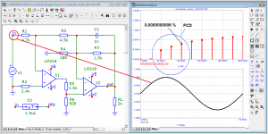
can you name the brands of amplifiers that were in the test?
What is the FSD level of the first amplifier and what is the second one?
Why does the second amplifier with TCD = 0.008% sound ugly?
Why does a high distortion tube amplifier have such a low RIMD (Reverse Intermodulation) noise floor? Much lower than an amplifier with THD = 0.008%
I would have to look it up, not sure I still have that article, but I am not going to let you draw the discussion to yet another subject, it's bad enough as it is.
This article is about Interface Intermodulation and I fail to see any connection with the discussion on FCD.
Please keep at the current discussion.
Jan
PS See attachment ...
Attachments

Last edited:
Could you clarify which article you are talking about? I may have read it, but it would be useful to refresh my memory, I think.
R.A. Brockbank and C.A.A. Wass, "Nonlinear Distortion in Transmission Systems," Journal of the Institution of Electrical Engineers, Vol.92, III, 17, p.45 (1945)
Eventually, Belcher quoted their work:
https://www.keith-snook.info/wirele...s-World-1978/A new distortion measurement.pdf (go ahead, ignore the warning, the link is safe to get the pdf)
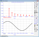
here is the distortion of the first period of the phase-shifted amplifier at the input
as you can see, the distortions of even such a castrated first period are negligible at the amplifier input, which cannot be said about the distortions of the same period at the output
as you can see, the distortions of even such a castrated first period are negligible at the amplifier input, which cannot be said about the distortions of the same period at the output
Attachments
Thanks)R.A. Brockbank and C.A.A. Wass, "Nonlinear Distortion in Transmission Systems," Journal of the Institution of Electrical Engineers, Vol.92, III, 17, p.45 (1945)
To all:
For example, I created the simplest single-pole model and fed it an ideal rectangular signal, which, as we know, has many harmonics. The graphs illustrate the shape of the output signal when such a signal is applied to its input and the difference between the input and output signals. In essence, this is something that is out of bandwidth. We see the characteristic shape of the difference signal, which can not be confused with anything. At its core, this is an integrator error, which I showed somewhere earlier in the topic in the form of a screenshot, which is also given by Sandi Todorov. If you look a little from a different point of view, this is the signal at the output of the low-pass filter, if it is given a rectangular signal at the input. But in any case, the meaning of the physical phenomenon is the same-limiting the rate of rise of the output signal by the filter circuit when applying an infinitely fast signal, ideally.
However, if we consider the amplifier simplistically as a link of the low-pass filter of the first order, it is worth noting that the useful signal supplied to the input is not in the suppression band, but in the passband and should not receive significant changes.
Why am I so verbose? Do we need to amplify what's left out if it doesn't fit our ears? Of course, we need some margin in both directions along the frequency axis, but without fanaticism and within a reasonable framework. For example, I previously gave in post 658 the justification of the upper frequency of amplified frequencies from the point of view of acoustics and scientific data on the audibility of the difference.First cycle distortion - Graham, what is that?
If someone has other data, then I will give concrete and reasonable counterarguments with links to scientific publications (not to marketing articles!).


Jan, thanks for the submitted drawings
unfortunately I only have 3 schemes:
Sony TA-N86
Sansui AU-D907
JVC A-X5
You needlessly react like that: "This article is about Interface Intermodulation and I fail to see any connection with the discussion on FCD."
Graham has repeatedly emphasized that the amplifier has two inputs (the output of the amplifier is also the input). Hiragi's tests are directly related to this topic - they are links in the same chain.
I join in the gratitude. Useful and eloquent illustrative material.PS See attachment ...
But remember this is Interface Intermod, in which the test signal is inserted into the output, NOT into the input. The input is shorted.
Jan
Jan
You needlessly react like that: "This article is about Interface Intermodulation and I fail to see any connection with the discussion on FCD."
Graham has repeatedly emphasized that the amplifier has two inputs (the output of the amplifier is also the input). Hiragi's tests are directly related to this topic - they are links in the same chain.
No, it is exactly necessary to react like this. Again, like you do all the time, you drag in stuff that has no bearing whatsoever on the reaction of an amp to a stepped input. The stuff you quoted are reactions of amps to test signals into the output with shorted input.
It is also the reason you are getting nowhere because you don't seem to be able to stay on topic and advance a discussion. Actually, you are constantly thread jacking your own tread!
Jan
Thanks)
To all:
For example, I created the simplest single-pole model and fed it an ideal rectangular signal, which, as we know, has many harmonics. The graphs illustrate the shape of the output signal when such a signal is applied to its input and the difference between the input and output signals. In essence, this is something that is out of bandwidth. We see the characteristic shape of the difference signal, which can not be confused with anything. At its core, this is an integrator error, which I showed somewhere earlier in the topic in the form of a screenshot, which is also given by Sandi Todorov. If you look a little from a different point of view, this is the signal at the output of the low-pass filter, if it is given a rectangular signal at the input. But in any case, the meaning of the physical phenomenon is the same-limiting the rate of rise of the output signal by the filter circuit when applying an infinitely fast signal, ideally.
However, if we consider the amplifier simplistically as a link of the low-pass filter of the first order, it is worth noting that the useful signal supplied to the input is not in the suppression band, but in the passband and should not receive significant changes.
Why am I so verbose? Do we need to amplify what's left out if it doesn't fit our ears? Of course, we need some margin in both directions along the frequency axis, but without fanaticism and within a reasonable framework. For example, I previously gave in post 658 the justification of the upper frequency of amplified frequencies from the point of view of acoustics and scientific data on the audibility of the difference.First cycle distortion - Graham, what is that?
If someone has other data, then I will give concrete and reasonable counterarguments with links to scientific publications (not to marketing articles!).
View attachment 906305 View attachment 906306 View attachment 906307
Can't find anything wrong with this.
Jan
Me too)Can't find anything wrong with this.
The main thing is to correctly interpret the results obtained and cut off the sources of potential errors. Specifically, I did not take the model of the amplifier, but a simple structure, even with perfect buffers I hung it on both sides, so that even the thought did not arise that somewhere something is not coordinated or something else. In principle, such a model cannot have nonlinear distortions, since it consists of basic primitives and passive components. Hence, we make a simple conclusion - the nature of the terrible pictures shown by Petrov is linear distortion as a special case of the effect of a step signal on an object with a limited bandwidth.
Of course, this is not for you, Jan, so I describe the idea in detail, but for those who will still read our topic later.
- Home
- Amplifiers
- Solid State
- First cycle distortion - Graham, what is that?