> xover inductors I could try, around the 4-5mh range.
What resistance?
How much power can you afford to waste?
Resistance in the amplifier choke is roughly "twice" as wasteful as resistance in a crossover choke. And air-core coils tend to have significant resistance (or very significant cost). However some >400Hz drivers (especially horn-loaded) are so loud that you don't need a heap of power.
Hey, use screw terminals and try all your coils! (Try first with a $3 squawker so you don't blow-up irreplaceable drivers.)
Not sure of the resistance of the coils, will need to dig them out and check. So this gets back to my basic question, is it better to use the lower resistance higher value coils (due to being P core) or lower air core....
So if I go with air core the trick is to get the lowest resistance I can find or buy, correct?
So if I go with air core the trick is to get the lowest resistance I can find or buy, correct?
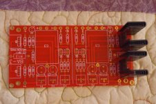
Dave,
Happy to hear the boards got to you.
Someone in this thread mentioned a choke CH-4 Bel Signal might be worth taking a look at, Digikey seems to have a better price than other suppliers.
Steve.
Happy to hear the boards got to you.
Someone in this thread mentioned a choke CH-4 Bel Signal might be worth taking a look at, Digikey seems to have a better price than other suppliers.
Steve.
EBay and microwave oven transformers are the low cost and great sounding solution.
Keyword search “microwave oven transformer md803”
Circa $30
They measure about 65mH and 0.5 ohms dcr. They are air gapped and good for about 10 A.
Keyword search “microwave oven transformer md803”
Circa $30
They measure about 65mH and 0.5 ohms dcr. They are air gapped and good for about 10 A.
My microwave transformer is 200mH but i haven't measure the resistans.EBay and microwave oven transformers are the low cost and great sounding solution.
Keyword search “microwave oven transformer md803”
Circa $30
They measure about 65mH and 0.5 ohms dcr. They are air gapped and good for about 10 A.
I will measure this.
Last edited:
Not sure of the resistance of the coils, will need to dig them out and check. So this gets back to my basic question, is it better to use the lower resistance higher value coils (due to being P core) or lower air core....
So if I go with air core the trick is to get the lowest resistance I can find or buy, correct?
The cored inductors need to be rated for more current than you are using.
An inductor used above its dc rating will drop to about air core levels as soon as the core saturates.
Bottom line, if the inductor is rated for the bias current, it probably is better.
if its not, an air core is better.
HTH
Doug
Microwave coil D.C resistans is 2 ohm.My microwave transformer is 200mH but i haven't measure the resistans.
I will measure this.
Microwave coil D.C resistans is 2 ohm.
Good for you I got Panasonic and the resistance is so low I can not measure PRECISELY with my cheap DMM.
I will measure the mH as soon I buy battery into that DMM.
I don't know if the resistance important or the mH?
I don't know if the resistance important or the mH?
The mH controls the low frequency roll off.
The resistance controls the efficiency.
HTH
Doug
I think in this application we need to look deeper into the circuite. . Looking back at the article we see that the frequency responce is only down about 1/3 of a DB at 20 hz using a 50 mh choke. But suppose we used that same 50mh inductor as the load in a common source amp in that case we would be down perhaps 6 DB at 20 hz. Why the huge difference you may ask well in our MoJo the the choke represents about 6.2 ohms of impedance and this will be in parallel with the speaker say 8 ohms for a total of ~ 3 ohms. But this will be driven by the IRF250 with it's source resistance of .17 ohms so in this case the inductance value shouldn't be of near as much concern as in a common source amp.
Ok, then how do things change for me as I plan to drive 16ohm compression drivers?
Do need to increase or decrease the inductance value? Bare in mind I only want above 400hz.
Do need to increase or decrease the inductance value? Bare in mind I only want above 400hz.
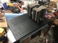
Sharing some progress on my MoFo. I’ll just say, this isn’t going to be quite a standard build. I plan on using most of the space in this 2U chassis. Curious to see if anyone can guess what I’m up to. 😎
Attachments
Ok, then how do things change for me as I plan to drive 16ohm compression drivers?
Do need to increase or decrease the inductance value? Bare in mind I only want above 400hz.
The choke is in parallel of the load (your 16 ohm driver) acting as a HP filter like in a 1st order series crossover.
Based on that you need a choke of around 6 - 7 mH, but with very low DCR, eg. 0.1 ohm would be good, lower even better.
Not sure how possible it is to find such a choke that can also handle the current of the MoFo.
Better approach IMHO would be to use whatever high current, low DCR choke you can find and then fit a cap that sets the HP point, in series with the positive input of the driver.
Calculate the value of the cap as for a 2nd order HPF.
It seems to be a high bias version of the MoFo?Sharing some progress on my MoFo. I’ll just say, this isn’t going to be quite a standard build. I plan on using most of the space in this 2U chassis. Curious to see if anyone can guess what I’m up to. 😎
2U used for a pre-amp...….maybe a tube pre?
Sharing some progress on my MoFo. I’ll just say, this isn’t going to be quite a standard build. I plan on using most of the space in this 2U chassis. Curious to see if anyone can guess what I’m up to. 😎
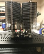
Love those CPU coolers with a single fan for sucking and blowing in one. The second one will get about 6C hotter air if that matters. (vunce tried same thing I think). I am guessing the rest of the 2U case is the Yarra/Melbourne preamp?
How will you fit any 67mH inductor inside a 2U though?
Sharing some progress on my MoFo. I’ll just say, this isn’t going to be quite a standard build. I plan on using most of the space in this 2U chassis. Curious to see if anyone can guess what I’m up to. 😎
Hi JW,
I used a similar setup with my Alpha20 with tunnel and the downstream cooler was approximately 6-8°C warmer.
The Big MoFo with cpu coolers works excellent!
Looking forward to seeing some progress pics 😉
Good stuff MEPER, X and Vunce! A tube pre is not in the plans but I do plan to make the pre somewhat "swap-able" in this case. The starting pre-amp is a very special one indeed. If you look in one of the photos you can just catch a glimpse. 😉
The chokes I'm using are Hammond 159zc's which fit nicely in a 2U chassis. I realize they only handle up to 2A but that should be fine for now. I was contemplating wiring (2) zc's in parallel per channel. In theory, it would halve the inductance and resistance, and split the bias current between the two chokes, correct? The chokes would be pretty close in proximity but I think I could potentially use an coupling to my advantage, in an additive configuration, yes?
Since this is an integrated build I also have an RJM Audio VSPS going in. We'll see how everything plays together.
And yes, I expected the rise in temp on the 2nd CPU cooler. I wanted to keep the top of the case as clean as possible so I went with a single fan for now. If temp becomes an issue, which I don't expect with 19.5v supply and 60mH 159zc's, I can always rotate the sinks and add a second fan.
More pics to come!
Ahh, with this power supply and cpu’s you’ll be “cool as cucumber”.
I wouldn’t worry about the downstream cooler. Keep the aesthetics clean and tidy 🙂
I looked pretty hard and it sure escaped my eyes what preamp you are planning.
The only swappable pre I know of is the Yarra? Or Aksa Lender?
The only swappable pre I know of is the Yarra? Or Aksa Lender?
- Home
- Amplifiers
- Pass Labs
- Build This MoFo!