Because its not the only way the phrase can be used. A friend can call another friend a MoFo.
There are other terms that probably should not be used. This is harmless.
There are other terms that probably should not be used. This is harmless.
"Sold out"??
Dang. I was really looking forward to my first attempt at an amplifier.
Apparently, I'm not so smart, and already ordered components, not thinking that I should have checked for the BOARD FIRST.
#facepalm
I guess I can spend the next week reading the other 208 pages of comments.
Many thanks to Mr. Rothacher and all those who chime in here to help.
Kind regards,
Drew
Hi discomb,
You can easily search for Vishay. Nowadays its the same thing. You may find them branded as BCs as i did in the past, but BC or Vishay are the same brand now. Look bellow. You can try something from here:
Axial capacitors | Mouser Electronics, Inc. Romania
Look the the Vishay datasheets.
They have a very very long lifetime, huge current capability and low esr and esl. Try two of 1000uF in paralell and see the difference. In the past i have wondered why Jlh used axial cap as the output on the jlh 69 but after i tried a 'Frako' 3300uf vs single or a couple of radial nichicon low esr i seen why he did that... Superb sounding from the axials..
Since then i was wondering if anyone feels the same, that big, chunky axial types sounds better that small or big radial types. And the axial doesnt have to be audiophile types. You may find from trial tests that there are 105-125-150 degreee celsius temp, industrial type caps that sounds the same as big names from the industry and at lower price.
Cheers
Here you are, some good examples:
Mouser Electronics, Inc. Romania
Mouser Electronics, Inc. Romania
Mouser Electronics, Inc. Romania
Or vishay sprague
Mouser Electronics, Inc. Romania
Mouser Electronics, Inc. Romania
Mouser Electronics, Inc. Romania
Mouser Electronics, Inc. Romania
Or vishay sprague
Mouser Electronics, Inc. Romania
Many thanks for your patient reply, @sergiu2009. This is my first project.
I have some caps on order; we'll see how they do. If they don't sound great, I can always replace them; I mean, that's part of the fun, right? 🙂
My blocker at the time was that I wanted to build on PCBs. Luckily another member has graciously stepped in with an offer, so I think I am past that hurdle.
Kind regards,
Drew
The ideea is that Vishay, formerly old Siliconix aquisition the Dale, BC, Sprague and so on brands and are found under Vishay noum+ the old brand initials..
Exactly thats the ideea. Fiddle with parts till you get it to YOUR taste.
Cheers
Exactly thats the ideea. Fiddle with parts till you get it to YOUR taste.
Cheers
not freq. linearity issue , just fact that you prefer even more 2nd harmonic in THD spectra, than MoFo is having
try listening with switched polarity of speakers , maybe you'll like it more
Ya, maybe my ears are used to tube amps.
I'll try the switching of polarity of the speakers. What does this accomplish - by switching polarity?
Thanks!
you can try 1000uf or more DC link cap , big expensive cap at first but the sound worth it. in theory you will have -3db at 20hz but in fact the Bass seems mre powerfull and fast 🙂
Thanks! I paralleled a 2UF film cap with the big e-cap and I liked it. Having totally replaced it with a film cap may be just what I need, albeit the size, LOL.
How do you calculate the -3dB with the output cap?
Hi discomb,
You can easily search for Vishay. Nowadays its the same thing. You may find them branded as BCs as i did in the past, but BC or Vishay are the same brand now.
Since then i was wondering if anyone feels the same, that big, chunky axial types sounds better that small or big radial types. And the axial doesnt have to be audiophile types. You may find from trial tests that there are 105-125-150 degreee celsius temp, industrial type caps that sounds the same as big names from the industry and at lower price.
Cheers
Yes, they sounded even better than the Frako,(I tried only the normal Frako that I got only) For some reason the old Philips to me sounded better than the newer BC. The plastic wrap already was pulled off.
I took out those 4700uF Philips from a used old British amplifier maybe because they were already burned in?? 😕
It made the whole sound airier, cleaner, had better control at low mids and bass compared to any other so-called audio caps.
Unfortunately, after I dismantled my SEWA (it only had a 7W and I did not have a good preamp, I used my Nakamichi Receiver pre) ad too much heat for that 7W at summer. I gave away those caps to Tyimo ex forum member. At least I bless him with those! 🙂 Great guy.
I believe it worth to try to get those Philips or BC.
Ya, maybe my ears are used to tube amps.
I'll try the switching of polarity of the speakers. What does this accomplish - by switching polarity?
Thanks!
Assuming you have both speakers on the same polarity (+ connected to +, - connect to -), switching both will not do much to the listening ear. However, if you switch just one of the speakers, holes will appear in the sound stage (if you can even get one at all), and various (mostly lows) frequencies will be missing or muffled (most likely), where there will be holes in the upper frequencies. This is my experience, YMMV, and there is google for better technical answers.
Hi Drew,
I think you will find the Mofo a fairly straightforward and fun build.
One think I will like to point out is an issue of inductor kick if you
disconnect the DC suddenly (say by pulling out the dc connector), which
can damage the mosfet. You can see the discussion in the posts around here:
https://www.diyaudio.com/forums/pass-labs/313649-build-mofo-143.html#post5574238
(I built mine with a small CRC between the DC connector and the Mofo PCB
and also I switch off the amp by unplugging at the AC end.)
Good luck with your build.
Dennis
Something to consider as far as "airieness".I have an amp that had 2nd harmonic 15db higher than the third harmonic.The sound was nice but a little"dark" and the highs weren't in balance with the bass.I adjusted the input buffer degen resistors to give me 12db difference.The result was more "airieness",highs are better,much nicer sound to my ears.I don't know if there is a way to adjust the Mofo's harmonic structure or if maybe your preamp is adding something not to your liking.Maybe someone with more knowledge can give some ideas.
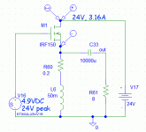
PRR if this was inductor loaded common source amp your calculations would apply but I believe when used as a source follower things may be drastically different. Just look back at the article and you see the amp is only down about 1/3 db at 20 hz.
That's small-signal response.
We may want large power at low frequencies.
me> 50mH will support 8 Ohms down to 26Hz.
Whichever end of the MOSFET we load at, 50mH at 25.5Hz is 8 Ohms reactance in parallel with the load. This bleeds-off the limited maximum current available from this amplifier. Maximum output is reduced.
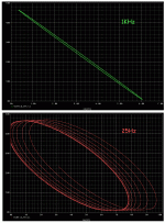
Here's plots. At 1KHz we get a near-linear loadline. At 25Hz we get a wide oval which, for the same level, clips at both ends, not the same, so bias-shift also.
Attachments
Hi all, I'm about to order the parts for my MoFo now I have PCB's sorted thanks to @wtl
As these will only be used for >400hz are there any component values that could be optimized taken we don't need low freq response? Maybe a different choke?
Also the power off spike scares me a little as my Yamaha 6681b diaphragms are unavailable, should I use a universal type speaker protector board?
Thanks
Somewhere is this thread there has been discussed using a smaller choke if bass response is not needed. Some has also implemented it and demonstrated it in this thread. I don't hear any sound in my speakers when I power MoFo off.
Hi nzlowie,
This might be useful:
MoFo inductor options for use above 1kHz only
Also I did not notice any power on/off noise with my mofo.
Cheers,
Dennis
This might be useful:
MoFo inductor options for use above 1kHz only
Also I did not notice any power on/off noise with my mofo.
Cheers,
Dennis
Also the power off spike scares me a little as my Yamaha 6681b diaphragms are unavailable, should I use a universal type speaker protector board?
Thanks
Hi nzlowie,
There are no noises or problems powering off on the AC side of the MoFo psu. It’s the sudden disconnect of the DC side (plug) that can potentially harm the Mosfet, install the Z1 zener diode. Install a small CRC between the
dc chassis input and the MoFo power input, it will store a bit of energy for a slower power down in the event the power plug was suddenly removed.
Happy Building 🙂
Vunce
Pass DIY Addict
Joined 2000
Paid Member
Yep, even a small 1,000uF cap of appropriate voltage rating across the DC input is enough to keep the collapse of the coil from killing the output mosfet if the DC end of the plug is pulled. My MoFo has no on/off thump at all.
Thanks guys,
I have a few xover inductors I could try, around the 4-5mh range. These are air cored but I have a couple of larger Jantzen P core, which would be better - smaller value air core or larger value P core? Or just go with Micheal's Hammond recommendation?
There was also a comment about reducing the output capacitor, suggested value for over 400hz or just use a film bypass cap on the 6800uf?
Thanks
- Home
- Amplifiers
- Pass Labs
- Build This MoFo!

