I was going to PM this, but someone else out here may be as helpless as me. Holy tiny SMD parts batman! Besides magnifying glasses and fine point solder tip which I have on hand, what is down and dirty skinny on soldering these tiny tidbits without specialized equipment? I figure once I have one pad down, the other two will be easier. Are these parts fairly immune to heat? What power should I dial my smaller Hakko down to?
Thanks,
Russellc
Thanks,
Russellc
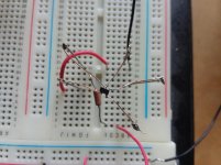
Helping hands and a bamboo skewer. I'll get a photo of my (completely hack) setup.
Don't turn the iron down too much, as solder flowing is what makes it all work.
Don't turn the iron down too much, as solder flowing is what makes it all work.
I was testing Idss of some 2sk2145, the dual version. I would have to find another way if I had many to do. Maybe some pads that the package can be pressed onto and take a reading.
How to solder these little things?
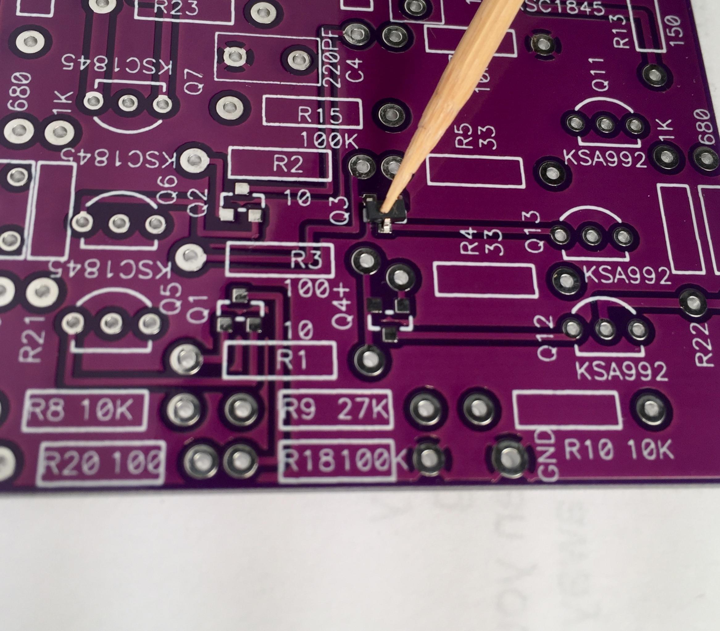
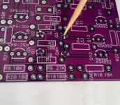
Put a small amount of solder on the pad then place the FET on top with enough pressure to hold it in place then heat the lead to melt the solder. Then like you said once the first is done the rest are easy.
How to solder these little things?
Put a small amount of solder on the pad then place the FET on top with enough pressure to hold it in place then heat the lead to melt the solder. Then like you said once the first is done the rest are easy.
Attachments
Helping hands and a bamboo skewer. I'll get a photo of my (completely hack) setup.
Don't turn the iron down too much, as solder flowing is what makes it all work.
I will await your sophisticated bamboo skewer laboratory setup....😀
Russellc
I was testing Idss of some 2sk2145, the dual version. I would have to find another way if I had many to do. Maybe some pads that the package can be pressed onto and take a reading.
How to solder these little things?
Put a small amount of solder on the pad then place the FET on top with enough pressure to hold it in place then heat the lead to melt the solder. Then like you said once the first is done the rest are easy.
Looks like a spider!
Russellc
I have been building some of XRK's designs he has on the forum and using his suggestion of a teflon coated plate and a small electric hotplate. Fairly easy using solder past and a pointed tool or toothpick.. For one off is ok but slow.
BDP's suggestion of tinning a pad and getting one tab soldered is brilliant. I just soldered the K209's on my other set of boards (for the big outputs, I'll have photos and info in the next day or two) and it worked great! Once you've got one leg down and the device won't move around, the other 2 are super easy.
The good news with the SMD legs is because everything is so small the heat transfer is practically instant. Wear your good close-glasses, keep your iron's tip clean and be sparing with solder. It's not as hard as it looks.
Sorry for the quick n' dirty iPhone photos...

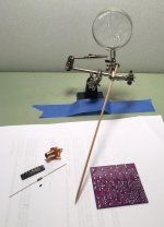
The super hack SMD station, made by someone who doesn't have any special tools for the job. The helping hands are taped to the bench so they don't move, the bamboo skewer is used to hold the teensy transistor in place while you solder the first leg. Tweeters (not photographed) or a small needle nose pliers are helpful for manipulating/moving the transistor.
Bamboo semiconductor retaining device, tapered actuating end shown.

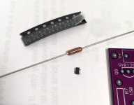
The standard 1/4w Dale resistors I like to use, shown for scale with the package of 8 shown above, and a single 2SK209 shown below. Don't sneeze. (Seriously) 🙂
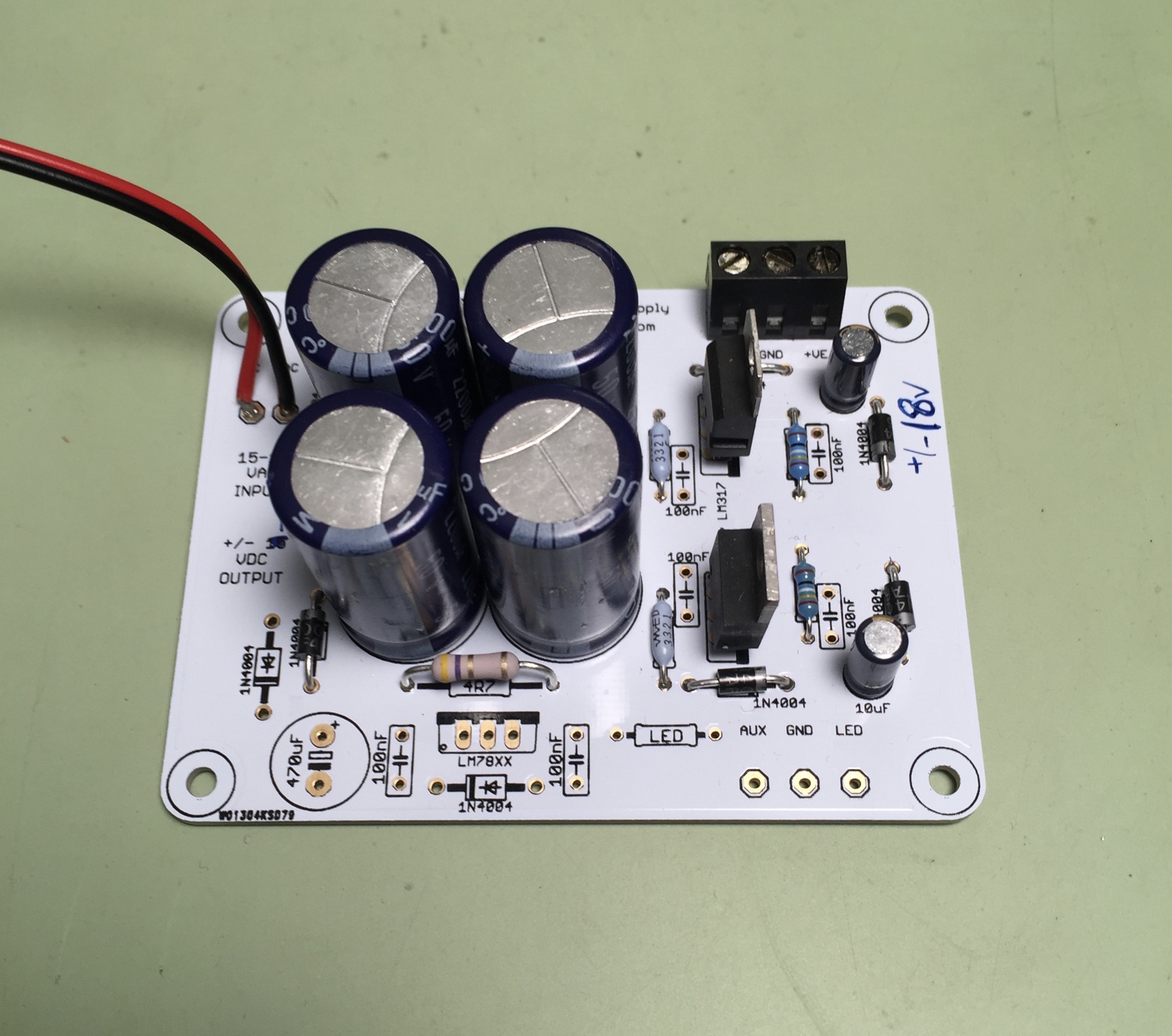
This is a neat PSU option, a board from Muffsy that runs of a 15-18 volt AC (AC, not DC, that's important) wall wart that makes +/-18v for the circuit. You can find them here - Muffsy Hifi Dual Power Supply V4 -Kit from muffsy on Tindie
If you want 18v you'll have to change 2 resistors on the PCB, the supplied resistors give 15v It's a standard 317/337 regulator implementation, a great choice for our needs.
You need to locally source the wall wart. If you buy the kit from Muffsy the parts are included and will have more and different bits than shown. (I bought a small quantity of empty PCB from him, the close-outs of his previous layout. He's also got a killer phonostage that the PSU is actually made for, it's worth looking at.)
The good news with the SMD legs is because everything is so small the heat transfer is practically instant. Wear your good close-glasses, keep your iron's tip clean and be sparing with solder. It's not as hard as it looks.
Sorry for the quick n' dirty iPhone photos...
The super hack SMD station, made by someone who doesn't have any special tools for the job. The helping hands are taped to the bench so they don't move, the bamboo skewer is used to hold the teensy transistor in place while you solder the first leg. Tweeters (not photographed) or a small needle nose pliers are helpful for manipulating/moving the transistor.
Bamboo semiconductor retaining device, tapered actuating end shown.
The standard 1/4w Dale resistors I like to use, shown for scale with the package of 8 shown above, and a single 2SK209 shown below. Don't sneeze. (Seriously) 🙂
This is a neat PSU option, a board from Muffsy that runs of a 15-18 volt AC (AC, not DC, that's important) wall wart that makes +/-18v for the circuit. You can find them here - Muffsy Hifi Dual Power Supply V4 -Kit from muffsy on Tindie
If you want 18v you'll have to change 2 resistors on the PCB, the supplied resistors give 15v It's a standard 317/337 regulator implementation, a great choice for our needs.
You need to locally source the wall wart. If you buy the kit from Muffsy the parts are included and will have more and different bits than shown. (I bought a small quantity of empty PCB from him, the close-outs of his previous layout. He's also got a killer phonostage that the PSU is actually made for, it's worth looking at.)
Attachments

Last edited:
Curved tweezers work great with a little quick chip flux. lay down some flux, position the component then rest the tweezers heal down and put pressure on the top of the component. bring in the pre-soldered iron tip and the flux will pull the solder into place.
The flux really helps with sneezes.
The flux really helps with sneezes.
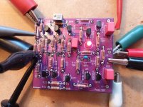
Completed the first board. 11mA in the output stage. 2mA for the current sources.
I soldered up the front end without Q3 and Q4 current sources.Then I placed the small FET on the pads and took a voltage reading across the 33 ohm source resistor. I went through the supplied FETS that Jim sent in the kit and they all measured 2.0 to 2.1mA.
Offset was easily set and stable. Gain was 3.7 (11.4dB) as expected.
Small 2nd harmonic at 2Vrms output.
Attachments
Thanks for showing your SMD apparatus! What was the TubeCad power supply you used in another post above? Not PS 19, which is what I think I used on BA3 preamp project...
Russellc
Russellc
The TubeCad PSU is something John made after a conversation at dinner this year at RMAF. It's a neat board and works very well. Email him, I think he said he had 30 boards made.
The TubeCad PSU is something John made after a conversation at dinner this year at RMAF. It's a neat board and works very well. Email him, I think he said he had 30 boards made.
Will do, what voltage am I looking for? Usually his Power supplies cover a few and one must be selected.
Thanks,
Russellc
- Home
- Amplifiers
- Pass Labs
- Wayne's BA 2018 linestage