B3 2800Hz because you also asked for it.
And Mario will be very happy, he is big fan 🙂
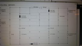
Schematic filter 21 B3 2800Hz

SPL 0deg filter 21 B3 2800Hz

SPL 15deg filter 21 B3 2800Hz

This is my last one. When all these are not good, then there is something not correct
And Mario will be very happy, he is big fan 🙂
Schematic filter 21 B3 2800Hz
SPL 0deg filter 21 B3 2800Hz
SPL 15deg filter 21 B3 2800Hz
This is my last one. When all these are not good, then there is something not correct
Last edited:
Can you similate the xover in the attachement?
Tomorrow I will do.
Either his expectations, amplifier, or both. The only way to find out would be to buy/rent a measurement rig, run some sweeps, then, I think, it will be clear.When all these are not good, then there is something not correct
Last edited:
thanks Paul, your job is admirable.
I'm understanding that may be there is an issue with woofer's data on .frd.
I tried to low the level of the tweeter on simulation of 1-2db's 'cause I was thinking about your +2db issue but the tweeter is ok: lowering its level on the simulation file causes the tweeter sounding too low. So I can say the tweeter sim is ok.
The issue may concern the woofer, 'cause in all simulation, using a target LR4 or B3 or anyelse on 85 db, the simulation requires a 1.8-2mH inductor to have a flat response on 85db.
But in reality, the 2.2mH inductor appears too low. So maybe the woofer is sounding louder than we see on the simulation, maybe for the baffle, maybe for the non-uniform and variable driver characteristics. It's well know that scanspeak produces variable parameters driver and whit different T/S from the datasheet. so maybe that the ones misurated by dibirama are quite different from mine.
At the end of the story, I think we should find a more reliable .frd file for 18w or trying to lower its level of about 1-2db in the simulation because after more than 20 xover tried, I'm understanding that the woofer plays too loud, the woofer is always over the the tweeter. with 2.7 inductor it goes on places but this need to perform a total re-adjustement of the entire crossover.
There is a design here in the forum, named Galtis which should be very good and uses ss d2905 9700 but the images of crossover are unavailable. Would be good to have a look a that design
Tweeter level is easily adjusted by ear - it has to play so you don`t hear a tweeter playing 🙂 If it screams for attention - "listen to my mighty treble" - then its too loud or crossed too low. Before determining the crossover frequency and function, you should measure it bare for harmonic distortion products. You`d then want to cross above them, especially above 3rd and 5th products. A very nice flat crossover which leaks odd order products would yield unpleasant sound which would become even worse at higher power levels. Same applies for woofer, often these would have rising 2nd order distortion in the 2-3Khz band which is not unpleasant but would add material to the source sound. You need that data before to start working on the best crossover interval. This tweeter also lacks ff in the gap and this may produce ringing around Fs. Sometimes a parallel resistor, as in most of Paul`s proposals, would be enough to suppress it unless you use it very low, like your idea of 1.7Khz LR4 (bad one if you ask me). Sometimes it may not and will need its own dedicated RLC circuit.lowering its level on the simulation file causes the tweeter sounding too low. So I can say the tweeter sim is ok.
Increasing the inductor would alter the low pass function but not that much compared to the capacitor. The cap has a much greater effect on it. I use a LR2 on my own speakers with 1.35mH inductor, I can get a LR4 with the same one by just increasing the capacitor. The inductor would have more play to the function chosen, a bigger one gets you a lower Q so roll off becomes earlier, thus it is used to address baffle step compensation.The issue may concern the woofer, 'cause in all simulation, using a target LR4 or B3 or anyelse on 85 db, the simulation requires a 1.8-2mH inductor to have a flat response on 85db.
At the end of the story, I think we should find a more reliable .frd file for 18w
We finally get there 🙂 Ask Troels if he would be willing to share his .frd of the 18W on the SP95 baffle. I would completely understand him if he says no or doesn`t reply, but he is a nice chap so I think its worth a try. The other way around (the right one) would be you investing some extra cash into a measurement rig. Once done, you can sell it in the swap meet and reduce the money spent.
Last edited:
Hi Mario, I just asked him for the .frd but he says he doesn't share the file anyway.
But, do you use the 18w? I don' t like low pendance filter like LR2 because there is a lot of audible overlapping between the drivers and the peak on 3khz (more pronounced off axis) make that frequencies audible 'cause the total power response is always the sum of direct and reflexed one. So if I have the 2khz beamed off axis and an off-axismore audible peak at 3khz , the total response will show a dip at 2khz and a bump at 3khz wich, as said, overlaps with tweeter response and make the resulting FR confused and bumped at crossing point.
I think simple LR4 on this woofer with inductor and capacitor is not enough for a level speaker, maybe it is good for a "budget" project. At the end of the story, I don't appreciate LR4 topology (inductor and cap on this woofer) and I don't like the sound.
I think that a B3 topology or a good calibrated LR4 with an RC in parallel with the inductor may be a better solution because make the roll off of the woofer more sweet and regular, and also lowers the audibility of that 3khz peak that is, in my advice, very critical at listening.
would you propose a filter topology? or help me in searching for commercial prooved designs like Sonus faber? I know that in many cases the drivers are customized, but we could make a proof.
regards
Last edited:
ANYWAY, I found these files for 18w8531 that are traced by the zaph page by someone.
I think they are very right because of the rising response from 400 to 1500hz not visible on the previous file.
so Paul, i invite you to simulate with this file, maybe we have found the issue!
I think they are very right because of the rising response from 400 to 1500hz not visible on the previous file.
so Paul, i invite you to simulate with this file, maybe we have found the issue!
Attachments
Last edited:
ANYWAY, I found these files for 18w8531 that are traced by the zaph page by someone.
I think they are very right because of the rising response from 400 to 1500hz not visible on the previous file.
so Paul, i invite you to simulate with this file, maybe we have found the issue!
Look to the differences of the 18W8531 infinite responses of the Scanspeak specification , Zaph and Dibirama. They are not so much different. It has no sense to do simualtions again with the Zaph curves.
Maybe more differences can be expected with the tweeter.
You have to get your measurements Cucicu in some way. I think we have done our best to do without but it is mission impossible. I have done it against my preferred WOW.
Or maybe the midwoofer is not good enough for your level speaker. Troels' comments on its SP95 are also not so good.

black: Scanspeak specifcation
green: Dibirama
yellow: Zaph
Yes I know.
When I charged that zaph response on my simulator, response was different. I ll post it in a hour.
It has a dip on 200-300 hz and a rising bump on 800hz till 1.tkhz.
Maybe it is measured on the box baffle and not on infinite ine. I think it looks closer to what i can listen to from my speaker.
When I charged that zaph response on my simulator, response was different. I ll post it in a hour.
It has a dip on 200-300 hz and a rising bump on 800hz till 1.tkhz.
Maybe it is measured on the box baffle and not on infinite ine. I think it looks closer to what i can listen to from my speaker.
Yes I know.
When I charged that zaph response on my simulator, response was different. I ll post it in a hour.
It has a dip on 200-300 hz and a rising bump on 800hz till 1.tkhz.
Maybe it is measured on the box baffle and not on infinite ine. I think it looks closer to what i can listen to from my speaker.
The Zaph frd is an infinite baffle response, I am very sure of that. It maps perfect on Dibirama and specification, look to my last posted plot.
ok.
I think we should take another direction.
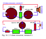
Can we try to make a clone of proac 2.5? troels made a clone paper using also the d2905/9500 tweeter wich has no ferrofluid; mine d2905/9700 has ferrofluid so it has a rising response over 10khz, which matches perfectly with original proac response.
I think we should take another direction.
Can we try to make a clone of proac 2.5? troels made a clone paper using also the d2905/9500 tweeter wich has no ferrofluid; mine d2905/9700 has ferrofluid so it has a rising response over 10khz, which matches perfectly with original proac response.
But, do you use the 18w?
Yes but my setup is very different from yours, my tweeter is recessed 34mm (physical time allginment) and uses a true LR2 with all tis benefits, and does not exhibit the ripple of the rectangular baffle because my baffle is very different 🙂 So, I`m not a good source of direct comparison to the SP95.
Paul, could you simulate this?
Is the good one, this time. I won'tell you nothing more 🙂
if you can, please, make a simulation
Is the good one, this time. I won'tell you nothing more 🙂
if you can, please, make a simulation
Paul, could you simulate this?
Is the good one, this time. I won'tell you nothing more 🙂
if you can, please, make a simulation
Hi Cucicu,
These are the results with the dibirama frd's
Schematic filter23 Proposal Cucicu

SPL filter23 Proposal Cucicu dibirama frd's

This is not really flat with the dibirama frd's but its sound is good you say.
So I think you have the non ferro fluid tweeter and secondly the baffle response has more boost.
Look to the simulation results of my own Leap frd's with non ferro fluid tweeter (specification Scanspeak) and using the Leap diffraction calculator. It is much more flat using these frd's now.
But for the same money I am completely wrong 🙂
SPL filter23 proposal Cucicu Leap frd's

Also this Cucicu, this morning I remembered I have measured the Scanspeak 18W8531 in almost the same enclosure with my Clio system outdoors. That was end 2007. And what do I see, it has more baffle boost than Zaph. But I have to control baffle width and driver position. When I know more about this I let you know and post the measurement.
Ok
But i obtain 2 different responses with dibiramas and zaph .
Very different, major difference is at the crossing point.
I ll post later but i can say that zaph frd and zma are the most correct. The filter i posted is made working on dibiramas files an it appeared good on sim. Also listening was very good and quiet, always better than the previous ones. But there was a lacking on the highs that I cannot explain by sim.
When i charged zaph files, same crossover, a 3db dip between 3khz and 4khz appeared. So now i am trying to adjust it but this is the way Paul. No overlapping, no paperish sound, very clean highs ( tweeter cut at 3200hz).
I lowered the 1 mh inductor drastically to 0.20mh and pumped the 4.7uf cap in woofer to 6.8uf. Now it is better, no dips at listening, no flat lines on the sim but is ok.
I think the last issue is to play with the 1mh inductor and the cap on the woofer that are very critical cause arr linked to a more/less presence of the mid range. Very critical and very audible. Now with 0.20mh and 6.8uf there is more cleareness on midrange but maybe it is too much. Make your proposal that we are on goal!!!!
Last edited:
I don't think you are going to do this with low order filters. 😱
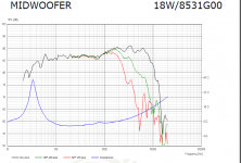
The rising response above 800Hz seems to dog all the Scanspeak 6" drivers.
What I did find is some impedance correction always helps. I used 7.5R and 10uF. That helped Troels' Proac 2.5 design a lot too.
But only a 4th order on both drivers could correct the response adequately. I actually used your ZMA and FRD files provided earlier.
Attachments
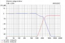

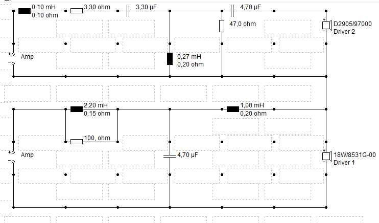
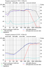
I'm actually not very bothered what the tweeter is, but used a 88dB G20SC to match yours. The woofer is a scanspeak 8531, because I used your ZMA and FRD files with a bit of fudging. The response seems to match the scanspeak data anyway. Time alignment was a bit guesstimate with your files. I could be wildly wrong on that. 😱

The theory says, once you get a LR4 curve on one driver, you just have to adjust the other driver filter for a matching LR4 result. And 4th order filters totally dominate individual tweeter response. The circuit is just what Boxsim optimiser came up with. It needs tidying up, but the 1.35R is a very critical component that works best when bigger IMO, because the impedance bump is ugly.
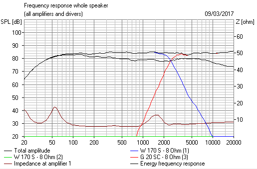
The theory says, once you get a LR4 curve on one driver, you just have to adjust the other driver filter for a matching LR4 result. And 4th order filters totally dominate individual tweeter response. The circuit is just what Boxsim optimiser came up with. It needs tidying up, but the 1.35R is a very critical component that works best when bigger IMO, because the impedance bump is ugly.
Attachments

- Home
- Loudspeakers
- Multi-Way
- Scan-Speak crossover help