hi paul, my simulation with dibirama's files matches perfectly with yours.
with 2.7mh/12uf (without the 4.7 resistor) phases is best.
I would ask you to simulate another filter but an LR4 at 1.7khz. I find it is the best crossing point. Maybe also 1.5Khz would be good. Could you?
thanks
with 2.7mh/12uf (without the 4.7 resistor) phases is best.
I would ask you to simulate another filter but an LR4 at 1.7khz. I find it is the best crossing point. Maybe also 1.5Khz would be good. Could you?
thanks
Last edited:
hi paul, my simulation with dibirama's files matches perfectly with yours.
with 2.7mh/12uf (without the 4.7 resistor) phases is best.
I would ask you to simulate another filter but an LR4 at 1.7khz. I find it is the best crossing point. Maybe also 1.5Khz would be good. Could you?
thanks
It will not make many sense if you choose now 1700Hz or 2000Hz at this moment. The point is you have to come to that reference filter based on your own exact measurements. But ok i have made a 1700Hz version, the power response is a little more flat, but this is my last one at this time 🙂.
Such kind of filter should sound ok. In case it is bad, i mean not balanced with too much high or low, then there is something wrong, that means still an acoustic problem or a big deviation of your drivers from specification.
Did you try already filter37?
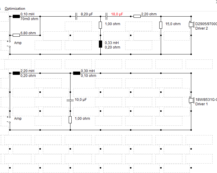
Schematic filter38

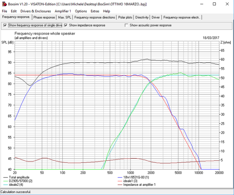
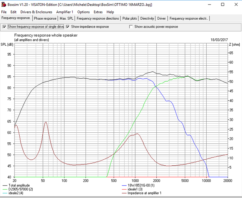
SPL filter38 LR4 1700Hz

Phase filter38 LR4 1700Hz

Thank you.
Yes i am listening to filter 37.
It appears really flat but i had to remove 0.10mh /6.8ohm inductor on tweeter
Now it s better to me.
Woofer sounds right. I think the tweeter response is not good on this baffle. It lacks on 3khz-5khz range.
When filtered like my previous filter (6.8uf/0.25mh-15uf/1.5mh) it has a heavy bump on 2khz but at the same time sounds more full and rich.
With your filter 37 it is more quite and less midy, no bump at 2khz but also a minor richness in the 3khz-5khz region.
A few months ago, together with a friend of me, I have done some comparison tests of different filter types on the same speaker using digital crossover. We made very accurate filters, very exact on target.
In our opinion a LR4 sounds more modest, without exesses than for instance a Butterworth 3 filter which sounds with more brilliance and life perception. Both are good filters, but the LR4 starts annoying a little after a long time listening. LR4 is playing a little more from distance, in contrary with the B3 that brings the music more in your room. That was our experience with that typical speaker.
Remark that the B3 has a flatter power response above 1kHz, but its dispersion is not symmetric w.r.t. the LR4. It is a choice you must make yourself. Therefore a digital filter is nice to have, you can switch between several (good) concepts.
It is the same impression i have.
So let s make a b3!
I had the same idea... it is already finished 🙂
I let the serial coil in the tweeter filter. You can also tune it, not by complete omitting but making the parallel resistor lower step by step.
Schematic filter39 B3 1700

SPL filter39 B3 1700 dibirama frd's

Phase filter39 B3 1700 dibirama frd's

i can't understand this. I made a B3 tracking at 2000hz.
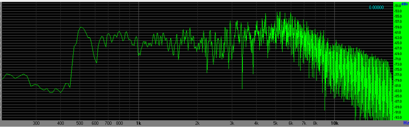
these are the sim and what I measure.
Why that bump at 1800hz?? I can't understand.
these are the sim and what I measure.
Why that bump at 1800hz?? I can't understand.
It can only be flat when the system is perfectly minimum phase, and that isn't the case. So you have to look to the phase also. The woofer is non-minimum phase outband, also due to the z-offset. The tweeter phase is leading to 90 degree at its resonance frequency of about 500Hz. You have to optimize for the best behaviour. I have done so for filter 39.
Last edited:
this is measurement of your filter39 B3 1700Hz
it matches perfectly with the sim. minor bump at 1800hz, minor dip between 2khz and 3khz.
this is more lively than previous. both are good. this 39 is more medious because of the bump on 1.8khz. if it is possible to lower it, I think this should be very fine.
it matches perfectly with the sim. minor bump at 1800hz, minor dip between 2khz and 3khz.
this is more lively than previous. both are good. this 39 is more medious because of the bump on 1.8khz. if it is possible to lower it, I think this should be very fine.
You can decrease C8 in the tweeter filter with small steps ... 6.2u ... 5.6u
In case it is a woofer issue you can increase R2 in woofer filter to 9.1E ... 10E
Or do both. You have to listen. With these modifications you stay close to target.
Is the measurement without the serial coil in tweeter filter?
In case it is a woofer issue you can increase R2 in woofer filter to 9.1E ... 10E
Or do both. You have to listen. With these modifications you stay close to target.
Is the measurement without the serial coil in tweeter filter?
Last edited:
ok.
the measurement is made with the serial coil in the tweeter arm. I think it is better than without it, but you have to consider that the mic is not compensated so the response from ca. 7khz is not real. high frequencies are pretty flat
the measurement is made with the serial coil in the tweeter arm. I think it is better than without it, but you have to consider that the mic is not compensated so the response from ca. 7khz is not real. high frequencies are pretty flat
Hi Cucicu,
When you are ready for another filter adventure, let me know. There is also the elliptical filter variant. That means more brickwall filter.
I have the best experiences with those filters. Since I use these filters in my system I cannot miss them anymore. They are sounding very fast, with a lot of life experience. But they have to be designed very accurate, otherwise it becomes a complete disaster.
The elliptical filter targets that I use are unique. There are already published other elliptical filter targets, but these ones I have created myself a time ago. I have a design ready for your speaker, just give a sign and I will post. But only if you built it, because I am curious about your findings about it.
Yes sure
I will try it when you will post
Ok Cucicu, here it is, elliptical 3rd order filter at 1700Hz. I am very curious for your findings 🙂.
IMO the sound has the qualities of both LR4 and B3, but it is playing even more fascinating, it's music. That is the experience of my realized elliptical systems up till now.
You can tune the high filter by changing R1 a little. 3.0E 3.6E 3.9E are also good values. Because we don't have your tweeter measurements
Schematic filter40 EL3 1700Hz

SPL filter40 EL3 1700Hz dibirama frd's

Hi paul
I tried your filter but in general there is an issue with this design. I don t like it. Now im trying the ekta 3way with 12m4631g00 as midrange.
If you wanna help me eith this deign just give me a sign. It is much better and i have already the speaker mounted.
Any help will be appreciated.
Thanks
I tried your filter but in general there is an issue with this design. I don t like it. Now im trying the ekta 3way with 12m4631g00 as midrange.
If you wanna help me eith this deign just give me a sign. It is much better and i have already the speaker mounted.
Any help will be appreciated.
Thanks
That filter has to be tuned very accurate. Without correct measurements it is not possible to realize.Hi paul
I tried your filter but in general there is an issue with this design. I don t like it. Now im trying the ekta 3way with 12m4631g00 as midrange.
If you wanna help me eith this deign just give me a sign. It is much better and i have already the speaker mounted.
Any help will be appreciated.
Thanks
For the Ekta, I will follow it, but to model again in Leap is a lot of work, and if again without the measurements will make it very difficult, especially for a three way system like this.
Ok. I think if you wanna make a try i can attach 12m frd and zma. I think this time will be simpler because i know well thi 3 way arrangement. The ekta design can be upgraded and many do this upgrade because midrange is crossed to high with woofer (ca.800hz) and too high also with the tweeter ( 4000hz). Your help would be appreciated for your experience in targets and phases adjusting. But it is ok. If you would like to try just tell me and i will share 12m files
Cucicu,
Try to create a good measurement setup and together with the simulations you will reach a much higher level of your speaker designs than now. It is also much more interesting to give support in that way. You have to think about it. I have a little non understanding about your way of working at this moment.
Try to create a good measurement setup and together with the simulations you will reach a much higher level of your speaker designs than now. It is also much more interesting to give support in that way. You have to think about it. I have a little non understanding about your way of working at this moment.
Hi.
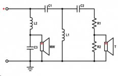
I built these loudspeakers with this crossover. Maybe someone can find the scheme I used useful. 😉
(PDF) Cajas acusticas Scan-Speak Kilimanjaro | Jesus Losada - Academia.edu
T: Tweeter Scan-Speak D2905/970000, normal polarity.
MW: Midwoofer Scan-Speak 18W/8531G00, normal polarity.
C1: Capacitor SCR-Audio PB820, MKP, 8,2 µF, 400 V.
C2: Capacitor SCR-Audio PB2200, MKP, 22 µF, 400 V.
C3: Capacitor SCR-Audio PB2200, MKP, 22 µF, 400 V.
L1: Coil Mundorf Mcoil L140, 0,27 mH, 0,13 Ω, Ø 1,4 mm, air core.
L2: Coil Mundorf Mcoil L140, 1,50 mH, 0,38 Ω, Ø 1,4 mm, air core.
R1: Resistor Mundorf MR10, MOX, 2,2 Ω, 10 W.
R2: Resistor Mundorf MR10, MOX, 10 Ω, 10 W.
Internal wiring: Sommer Cable SC-Nyfaz, 2 x 4,0 mm2.
Attachments
- Home
- Loudspeakers
- Multi-Way
- Scan-Speak crossover help