Thank you i will have a look.
With 0.10mh inductor response of tweeter is more detailed than without it. Maybe it makes a drop over 20khz but in general i am preferring with it.
I had an issue with tweeter level. Finally I manged to allign woofer . Could you simulate this? Now it s good but at fft measurement I have a bump on 4khz-10khz and can t understand if it is a mic issue or the reality.
Xover is (sorry i cant attach images at the moment):
Woofer 4rth order: 2.7mh with 47ohm in parallel/4.7uf to gnd/ 2.2 mh/6.8uf to gnd
Tweeter: 0.10mh-5.1ohm-3.3uf/0.25mh to gnd-6.8uf.
This config is alligned and no more woofer issues but maybe there is a phase problem in the crossing point with tweeter. Thank you
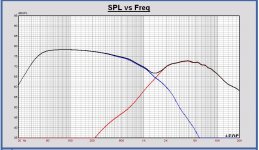
This is the simulation. I have used Leap frd for woofer and dibirama for tweeter frd. There is a power boost at 4-5kHz, just like you measure it.
There is some phase aligning above 3kHz. Below 3kHz the drivers become more and more in anti-phase.
For me it is difficult to give comments on this, because i don't hear the results. IMO you have to be closer to some standard designs. Do you have now a second speaker to compare with during your listening tests? During tweaking you should to go back sometimes to a reference design or speaker.
You did find filter 06 a "damn good" one. It is almost flat with the woofer Leap frd.
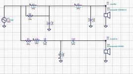
Schematic filter34
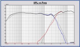
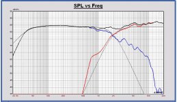
SPL filter34 and LR4 2800Hz targets
Phase filter34
Grey curve is LR4 2800Hz target phase
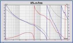
Electrical tranfers filter34
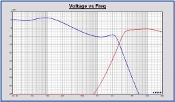
Power response filter34
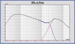
SPL filter06 and LR4 2000Hz targets
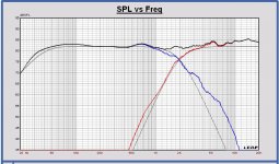
I understand Paul. i had a morning of measurements and saw the woofer is not good simulated. What the simulator gave me perfectly on phase was in antiphase when measuring. I also checked the polarity of tw and woofer.
Right now I made a big step up, woofer needs 3rd order and tweeter needs absolutely 2nd order. No way. That is the issue.
Now im listening to
Woofer:1.7mh/6.8uf to gnd/0.47mh
Tw:5.1 ohm-5.6uf/0.30 to gnd.
Drivers are same polarity.
Could you simulate this? If it works there are many similar designs to look at.
Thank you very much Paul
Hi Cucicu,
Maybe better that you first try to find out the best design you are really stisfied with and I will simulate that one. It is too much to simulate each step. I think you can understand.
Maybe better that you first try to find out the best design you are really stisfied with and I will simulate that one. It is too much to simulate each step. I think you can understand.
Paul
I have mounted the series xover here
http://www.diyaudio.com/forums/mult...8w8531-d2905-97000-crossover.html#post5015750
With minor mods. L2 is 2.7mh
Cz can be variable from 5.6 (more mids) to 12uf (less mids).
R1 is 3.9ohm
The cap on the tw zobel is 1uf.
Right now i am using it with cz=5.6uf, maybe mid are a little forward. If you try simulating i think we are on goal. Better of all the xover listened. The only issue can be cZ.
THANKS
Paul
I have mounted the series xover here
http://www.diyaudio.com/forums/mult...8w8531-d2905-97000-crossover.html#post5015750
With minor mods. L2 is 2.7mh
Cz can be variable from 5.6 (more mids) to 12uf (less mids).
R1 is 3.9ohm
The cap on the tw zobel is 1uf.
Right now i am using it with cz=5.6uf, maybe mids are a little forward. If you try simulating i think we are on goal. Better of all the xover listened until now. The only issue can be cZ that has to be regulated for alligning 1khz range.
THANKS
Paul
I have mounted the series xover here
http://www.diyaudio.com/forums/mult...8w8531-d2905-97000-crossover.html#post5015750
With minor mods. L2 is 2.7mh
Cz can be variable from 5.6 (more mids) to 12uf (less mids).
R1 is 3.9ohm
The cap on the tw zobel is 1uf.
Right now i am using it with cz=5.6uf, maybe mids are a little forward. If you try simulating i think we are on goal. Better of all the xover listened until now. The only issue can be cZ that has to be regulated for alligning 1khz range.
THANKS
Cucicu, also filter 29 with some changes to the Rabbitz filter, was technically ok. It is a LR2 at 2000Hz. Phase aligning is good. I am not so surprised that it sounds good.
Simulated with dibirama frd's.
Schematic filter 35
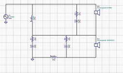
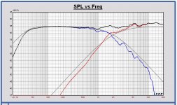
SPL filter35 LR2 2000
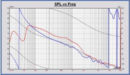
Phase filter 35 LR2 2000
Ok very good.
Would you suggest some modifications for tweeter arm? It doesn t seem flat from simulation but with original values for zobel ( 4.7ohm+3.9uf) of tweeter and with R1=4.7ohm it sounded dark.
Would you suggest some modifications for tweeter arm? It doesn t seem flat from simulation but with original values for zobel ( 4.7ohm+3.9uf) of tweeter and with R1=4.7ohm it sounded dark.
Ok very good.
Would you suggest some modifications for tweeter arm? It doesn t seem flat from simulation but with original values for zobel ( 4.7ohm+3.9uf) of tweeter and with R1=4.7ohm it sounded dark.
No ideas for modifications. Changing some components have impact on both driver SPL's for this type of filter.
Maybe your tweeter has a little lower level than the dibirama frd's.
When I see an interesting test to do, I let you know.
Thanks.
Paul
I have a suspect. I hope all this can be helpful for anyone interested in this building.
The baffle step should be at around 500hz for a 6.5'' driver on an 22.5cm wide baffle.
So it means that all frequencies under 500hz will be attenuated because of this phenomenon.
It means also that over 500hz we should have a boost of some db's till the crossing frequency. So baffle step creates a rising response over 500hz.
In reality, what I measured, is a big bump on 50-100hz because of the room gain, and this is more than normal.
I would expect , from simulations, a loss of power between 100-500hz and a rising response starting from 500hz and also a bump at 800hz due to impedance little peak of woofer, and also a dip at 750hz due to the suspension, as Mario said many posts ago.
The reality is different because i measure the bump due to the room gain (50-100hz) and a bump at 200-400hz.
From 500 hz measured response is quite fate, there is also the dip a 750hz but not the bump at 800hz. Starting from 500hz the response is quite flat. Minor bump between 1khz and 2khz but it depends on the woofer.
Paul
There is certainly an issue with z-offset of the woofer in the simulation.
I set it 24mm right now but is certainly wrong. Do you know its value exactly?
There is certainly an issue with z-offset of the woofer in the simulation.
I set it 24mm right now but is certainly wrong. Do you know its value exactly?
Thanks.
Paul
I have a suspect. I hope all this can be helpful for anyone interested in this building.
The baffle step should be at around 500hz for a 6.5'' driver on an 22.5cm wide baffle.
So it means that all frequencies under 500hz will be attenuated because of this phenomenon.
It means also that over 500hz we should have a boost of some db's till the crossing frequency. So baffle step creates a rising response over 500hz.
In reality, what I measured, is a big bump on 50-100hz because of the room gain, and this is more than normal.
I would expect , from simulations, a loss of power between 100-500hz and a rising response starting from 500hz and also a bump at 800hz due to impedance little peak of woofer, and also a dip at 750hz due to the suspension, as Mario said many posts ago.
The reality is different because i measure the bump due to the room gain (50-100hz) and a bump at 200-400hz.
From 500 hz measured response is quite fate, there is also the dip a 750hz but not the bump at 800hz. Starting from 500hz the response is quite flat. Minor bump between 1khz and 2khz but it depends on the woofer.
Hi Cucicu,
Here are some plots about this item. Some comparing measurements and simulations of the woofer in its cabinet in free field.
In 2007 I have done a Clio measurement outdoors of almost the same speaker as yours. With the bottom of the speaker at 150cm heigth. Probably an older version of the 18W8531 and the enclosure was a little smaller than yours, 21.5cm width.
Just to think about...
Bafflestep calculated with Babgy diffraction calculator
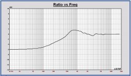
Response in enclosure on infinite baffle (pink), Leap simulation (red) and Clio measurement (green)
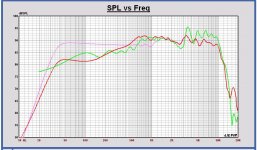
Response in enclosure on infinite baffle (pink), Zaph ZRT (brown) and Clio measurement (green)
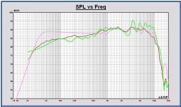
Response in enclosure on infinite baffle (pink), Bagby calculated diffraction (yellow) and Clio measurement (green)
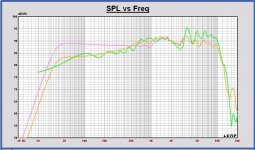
Response in enclosure all
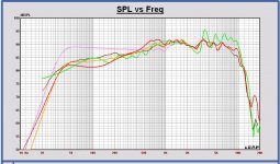
IMO the Bagby diffraction simulator is not so bad, but you cannot calculate more complex enclosures.
With this enclosure Leap has some problems. It is the first time I see these differences with a Clio measurement. I will try to find what the reason is...
Paul
There is certainly an issue with z-offset of the woofer in the simulation.
I set it 24mm right now but is certainly wrong. Do you know its value exactly?
24mm can be compensated by a 6 degrees tilt of the speaker behind. Or by listening 40cm downwards at 3m, that is at 50cm heigth 🙂.
Not compensating the offset affects the SPL on axis but not the power in the room.
It is diificult to compensate in a passive filter. Therefore a lower crossover point is also a better choice.
No, I don't know the offset value, it must be measured.
I measure the offset with the drivers on IEC baffle and the microphone at exact the same position for both. I compare the start time of the impulse repsonses of the drivers.
Last edited:
Ok.
I found definitive crossover. I will post later if interesting.
I can only say these are great drivers!
I found definitive crossover. I will post later if interesting.
I can only say these are great drivers!
I found definitive crossover. I will post later if interesting.
I can only say these are great drivers!
Nice, let's hope this goes on... 🙂
I ll.post it when i will absolutely sure...give me some days to be sure.
At measurements is very flat, from 200 to 5khz i can say this is quite sure. I measured fft at 1mt and pink noise. Fully sound and flat. I don t know if it could be a matter 🙂 normally, people dont like flat speakers
At measurements is very flat, from 200 to 5khz i can say this is quite sure. I measured fft at 1mt and pink noise. Fully sound and flat. I don t know if it could be a matter 🙂 normally, people dont like flat speakers
24mm can be compensated by a 6 degrees tilt of the speaker behind.
Problem is this z-offet is more like 32-34mm. I did a stepped baffle with this woofer with 22mm z-offset and after measurements, the offset appears very close to the values above. This is why I sugested the WG300 waveguide as it would recess the tweeter by 34mm which appears close to perfect. Otherwise it can be compensated this way but some crossovers may put you close to the vertical nulls they exhibit if you listen far anough 🙂
Thanks mario.
Sorry for the delay but i ve been out for working.
Hi Paul, after many trials i can say the paperish sound was due to a lack of damping material rearside the woofer.
So, all the xover tried have been lost work!
Now i can say that the midy sound is over, woofer works properly. Correct files are zaph's ones and also dibiramas are good.
Now im trying zaph design for woofer and 4th order on tweeter for phase matching. Data seem correct, when I have the perfect reverse null on the simulator i have also the perfect stereo image on speaker.
Now it is just a matter of tonal balance. Mino changes needed.
The actual xover is:
Woofer 2.7mh/10uf--4.7ohm to gnd
Tweeter is 4.7ohm--6.8uf/0.25mhto gnd--15uf/1.5mh to gnd.
Woofer z offset is 32mm as mario suggested.
Paul can you simulate and help me?
Without the 4.7ohm on the woofer, sound is mor midy in the 800-2000hz.
Thank you
Hi Paul, after many trials i can say the paperish sound was due to a lack of damping material rearside the woofer.
Hi Cucicu,
That is a nice progress in the design. Hopefully that is all for the acoustics...
I have simulated your filter and compared with LR4 targets. It can be better. IMO, at first you should make a technical perfect filter as good as possible and after that do some tweaking with the help of simulation. You have to tune around a reference otherwise you will never realize the ultimate design. Designs that are almost correct, you can make hundreds of them, and they have all good points but also bad points. My experience is, when you make a very good design, that means based on measurements, on a target, you can reach a result that you can hear that everything becomes nicely in balance. And that is not possible by listening only...
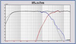
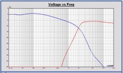
I have also made a design, a LR4 at 2000Hz, but better on targets (in the assumption there is a good map of your drivers on the dibirama frd's).
Your actual filter
Schematic filter 36
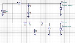
SPL filter 36 LR4 2000 dibirama frd's
Phase filter 36 LR4 2000 dibirama frd's
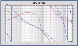
target in grey
Electrical transfers filter 36 LR4 2000
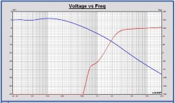
New design
Schematic filter 37
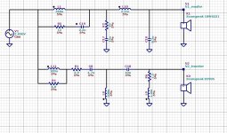
SPL filter 37 LR4 2000 dibirama frd's
Phase filter 37 LR4 2000 dibirama frd's
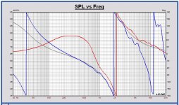
target in grey
Electrical transfers filter 37 LR4 2000
Last edited:
- Home
- Loudspeakers
- Multi-Way
- Scan-Speak crossover help
