Balanced input, 30Hz 12dB/oct low cut filter, clip limiter, volume control, signal-power-clip-protect led display and +/-18V regulator all this circuit on single pcb thanks to Willy.
niiice 🙂
selectable SE/balanced input ?
input impedance ?
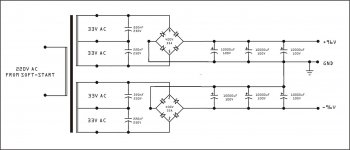
Most of people can not find 120V or 160 V capacitors in their place, 10000uF/63V is easy to find anywhere for lower price than any other capacitor. Best solution is to reduce rail voltage to +/-95V and use standard PSU circuit with 6x10000uF/100V capacitors.
agree. the little extra power is just not worth the cost.
i m going to built apex BA1200.is their any mistake in the circuit or pcb?or it is no problem good...please someone reply me...
@tinitus will you be using fans blowing in from underneath ?
Can't wait to see your progress as time passes.
Regards
Can't wait to see your progress as time passes.
Regards
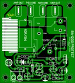
10k must be hot (1.5W disipation), you can use 5W resistor.
Here's Rev1.2 using 10K/5W resistor.
Regards,
Attachments
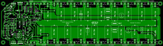
Balanced input, 30Hz 12dB/oct low cut filter, clip limiter, volume control, signal-power-clip-protect led display and +/-18V regulator all this circuit on single pcb thanks to Willy.
Heres the file's....
Attachments
-
APEX BA1200 Input & Display Rev1.4 PCB.pdf35.1 KB · Views: 1,655
-
APEX BA1200 Input & Display Rev.1.4 Silk.pdf68.3 KB · Views: 1,589
-
APEX BA1200 Input & Display Rev1.4 PCB Mirror.pdf35.1 KB · Views: 1,574
-
APEX BA1200 Input & Display Rev1.4 Gray.pdf98.2 KB · Views: 1,814
-
 APEX BA1200 UNPUT DISPLAY Rev1.4 Green.jpg704.5 KB · Views: 2,981
Protect pcb...
Protect Files...
Attachments
Hi Willjj78
greetings thanks for the pdf files the project can now move on
warm regards
andrew lebon
greetings thanks for the pdf files the project can now move on
warm regards
andrew lebon
@tinitus will you be using fans blowing in from underneath ?
have thought about it 😉
hope the natural convection will work
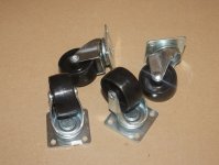
but I will definately have wheels 😀
Attachments
Heres the file's....
Thank you so much Wiljj78 for being so generous...🙂

Attachments


Last edited:
Apex,
You have right, I have to give up the 2U high version. Unfortunately the toroids are so big (200mm dia, and 76mm high, 2kVA), and there is not enough space for the heatsinks 🙁
Maybe some downscaled version will born...
Sajti
You have right, I have to give up the 2U high version. Unfortunately the toroids are so big (200mm dia, and 76mm high, 2kVA), and there is not enough space for the heatsinks 🙁
Maybe some downscaled version will born...
Sajti
tinitus,
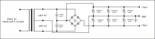
What difference does the center tap and and 220nf caps make to the circuit. Will it be more positive as just not to use the center tap ?
What difference does the center tap and and 220nf caps make to the circuit. Will it be more positive as just not to use the center tap ?
i have 2pcs 12,000uF 63V filter capasitor..what is the maximum voltage of transformer do i used for this filter..is it ok if i used 50- 0 -50 AC ??i plan to build this circuit
tinitus,
What difference does the center tap and and 220nf caps make to the circuit. Will it be more positive as just not to use the center tap ?
just because of available trafos, series connected, thats all 😉
mile shows it like that for the highest power, for the same reason, available trafos
might be ok to use only one 220nf on each trafo
but someone suggested that series connected trafos should better have two 'snubber caps'
I think snubber resistors are still missing
i have 2pcs 12,000uF 63V filter capasitor..what is the maximum voltage of transformer do i used for this filter..is it ok if i used 50- 0 -50 AC ??i plan to build this circuit
if its you first amp I would suggest smaller amp
your 63V caps would be fine for 100watt amp
use max 40V trafo
- Home
- Amplifiers
- Solid State
- 1000W Simple PA Amplifier