the BC560 can also used by nearly direct replace. To reduce the voltage (Vce Voltage) only two additional resistors must be introduce in the collector lines. As an additional wanted effect occurs a lower thermal value above ambient (less power loss) even by enhance the idle current through the input differencial amp (3-5mA is a better value for good sound than only 1,3mA - the currently value).
This I have often realized by several high voltage audio power amps like NAD to avoid burned PCB areas arround the input stage with TO92 small signal transistors.
I use 3-5mA only for J-FET input differencial amp, for BJT 500uA-1,5mA for different VAS topology.
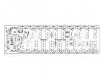
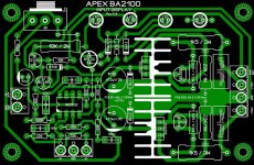
Time will show but I think that BA1200 will be popular diy amp. Single side pcb size 75x260mm with 20 outputs, power can be scaled... if I made different circuit nobody want to build it 🙂
Last edited:
I would rather say, that most developers of currently available typical hifi amplifier (so called Ultra High-End Audio power amps) don't understand, what makes a good amplifier and what makes a bad amplifier.Apex,
I suggest you consider the audience you have attracted.
The vast majority looking at your designs are only there because you publish high power designs. These same Power hungry Members in general do not understand what makes a good amplifier and what makes a bad amplifier. All they want is silly power ratings.
The evidence for that is very easy: Currently available amps with sonic performance like Passlabs or Halcro are very hard to find.
At right calculation by apexaudio's circuit topology together with well dimensioned power supply and top quality caps one will get excellent soundquality in all respects.
When one have typical public address power amp devices with bad sound, the main reason isn't the fact, that this amp is a high power version and was designed only for stage. The main reason is mostly the fact, that there are the cheapest available main electrolytic caps in use.
If you had read the articles written by Mr. Nelson Pass carefully, you would know that the height of the output voltage and power only determines the maximum undistorted SPL at a certainly speaker, and not the sonic quality itself.
for more simple design than this here, check out the MJR amp topologies:I want keep it simple.
http://www.angelfire.com/ab3/mjramp/index.html
Last edited:
for more simple design than this here, check out the MJR amp topologies:
There is nothing similar and more simple than this here
Attachments
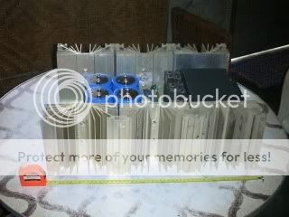
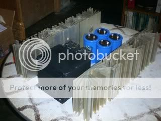
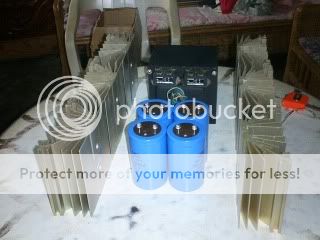
i am a sucker for power...the power traffo alone weighs in at 21kgs....filter caps are 3inch cans of 47,000ufd/100volts...
2 bridge rects rated for 72 amps each.... 😀
2 bridge rects rated for 72 amps each.... 😀


i am a sucker for power...the power traffo alone weighs in at 21kgs....filter caps are 3inch cans of 47,000ufd/100volts...
2 bridge rects rated for 72 amps each.... 😀
Me too, I don't like to use tricks like SMPS and class H , D , TD... to get this power, simple just use heavy metal 🙂
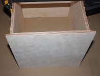
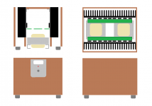
^is that your amp box?
He wants to make it very very simple.
the whole amp can be lifted out as a complete unit
Attachments
tony, is that transformer your own or purchased ?
i made it back in the 80's, EI center leg is 2 1/4 in stacked to 5 1/2 inches...
it took 2 of my brother in laws to help me wind the coils....
#12 primary and #10 SCC magnet wires....😀
looks good Tony...you got the heavy duty parts
since your supply caps are 100V types, I suppose you will stay low too 😀
since your supply caps are 100V types, I suppose you will stay low too 😀
yes i do...😀
actually what i wanted to do is a 500 watter into 1 ohm power amp...looking at Mile's schemo, they look the same except that my rails are about +-50volts...
actually what i wanted to do is a 500 watter into 1 ohm power amp...looking at Mile's schemo, they look the same except that my rails are about +-50volts...
Hi Apexaudio
greetings nice pcb many thanks to Willj for all the hard work in designing the pcb can you share pdf file of input limiter pcb
warm regards
andrew lebon
greetings nice pcb many thanks to Willj for all the hard work in designing the pcb can you share pdf file of input limiter pcb
warm regards
andrew lebon

this supply will only see 15.000uF pr rail. that is a little on the low end. also the total ripple current will be low. and ESR high. one will need BIG caps to connect it like this. maybe 22.000uF and twice as many. so the price will be the same as if one use 160V caps🙂
this supply will only see 15.000uF pr rail. that is a little on the low end. also the total ripple current will be low. and ESR high. one will need BIG caps to connect it like this. maybe 22.000uF and twice as many. so the price will be the same as if one use 160V caps🙂
Most of people can not find 120V or 160 V capacitors in their place, 10000uF/63V is easy to find anywhere for lower price than any other capacitor. Best solution is to reduce rail voltage to +/-95V and use standard PSU circuit with 6x10000uF/100V capacitors.
excellent work
Thanks for sharing your design. Since it is more reliable with the advice of apexaudio.
Sure! Here it is......
Regards,
Thanks for sharing your design. Since it is more reliable with the advice of apexaudio.
good job
after rereading I think this is the end of the voyage. Thank you.

Thanks Nazir...I'm using Sprint Layout 5, here's the file.
after rereading I think this is the end of the voyage. Thank you.
- Home
- Amplifiers
- Solid State
- 1000W Simple PA Amplifier