Unless my ears and simulator totally lie , TMC stuart's way works VERY well. It makes my OP's sound like listening to the drivers through headphones. 🙂
The TMC feedback resistor value is the biggest factor in thd reduction , 1:2 and up for the 2 capacitors is superior to 1:1 as well. The 2 attachments (below 1/2) speak for themselves. Another interesting thing I've played with is to bias the OPS undesirably (20mA and below) ... TMC still gives a drastic improvement to the sound. I'm absolutely sold on it ... 🙂
OS
Attachments
its handy to put these on the same plot - use the .step functionality
.step param tmc LIST 1 1e6
and for the added R,C values:
{tmc*220p}
{tmc*560}
the 1e6 factor makes the C practically a short and the R an open for the purposes of compensation
you could also adjust the Cdom for same gain intercept frequency with another value equation
you could also step a Vsource that controls a SW element
Last edited:
So the "1" just multiplies values 1:1 and when you step to 1e6 everything in brackets gets multiplyed by 1M , making the resistor 560M and the cap 2.2F (a short -"millerwise") 😎
Thanks for the explanation, JCX. handy !!
I use ".step param" a lot to refine component values. Some may scoff at the power of the simulation , but the resulting
real world amp performs very close to what the sim predicts.
OS
Thanks for the explanation, JCX. handy !!
I use ".step param" a lot to refine component values. Some may scoff at the power of the simulation , but the resulting
real world amp performs very close to what the sim predicts.
OS
Last edited:
TMC capacitor ratio
Hello Edmond
How do you determin the optimum capacitor ratio for TMC. Is there an optimum value for the resistor and how do you determin this.
Regards
Arthur
I repeat, can we now return to the previous topic, i.e. the capacitor ratio of TMC, please?
Hello Edmond
How do you determin the optimum capacitor ratio for TMC. Is there an optimum value for the resistor and how do you determin this.
Regards
Arthur
Hello jcx
Just out of curiosity have you designed and built low THD power amps.
Regards
Arthur
Just out of curiosity have you designed and built low THD power amps.
Regards
Arthur
TMC capacitor ratio
Thanks Pete!
It's always nice to hear that my tricks not only works in the virtual world of a simulator, but also works in real life. 🙂
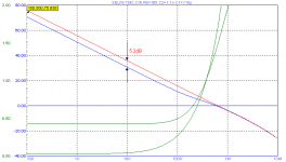
Regarding the capacitor ratio, I've run another sim, with a 1:1 ratio (C1=C2=200pF) and a 1:10 ratio (C1=110pF & C2=1.1nF). Both combinations give the same roll-off at HF, as they have the same equivalent series capacitance, i.e. 100pF. I've also adjusted Ri in order to get the same transition frequency (370kHz). So we may assume that the conditions with regard to stability are similar for both cases.
Now, let's have look at the global loop gain (see pic). At audio frequencies this loop gain is 5.2dB lower for a 1:1 ratio (blue curve) compared to the 1:10 case (red curve).
As pointed out already (see: http://www.diyaudio.com/forums/soli...erview-negative-feedback-303.html#post2355163 ), the difference in loop gain is not without consequences. Distortion and slew rate figures will be affected accordingly. By using a 1:1 ratio, about half of the potential improvement is thrown away.
BTW1, the picture below is about the same as in D. Self's article on TMC. He also did mention the loss in loop gain of almost 6dB. Yet he seems to take it for granted, instead of simply change the capacitor ratio. Why?!
BTW2, the green curves depict the ratio of currents through C2 and Ri. The transition frequency is where both currents are equal to each other.
Cheers,
E.
Unless my ears and simulator totally lie , TMC stuart's way works VERY well. It makes my OP's sound like listening to the drivers through headphones. 🙂
The TMC feedback resistor value is the biggest factor in thd reduction , 1:2 and up for the 2 capacitors is superior to 1:1 as well. The 2 attachments (below 1/2) speak for themselves. Another interesting thing I've played with is to bias the OPS undesirably (20mA and below) ... TMC still gives a drastic improvement to the sound. I'm absolutely sold on it ... 🙂
OS
Thanks Pete!
It's always nice to hear that my tricks not only works in the virtual world of a simulator, but also works in real life. 🙂
Regarding the capacitor ratio, I've run another sim, with a 1:1 ratio (C1=C2=200pF) and a 1:10 ratio (C1=110pF & C2=1.1nF). Both combinations give the same roll-off at HF, as they have the same equivalent series capacitance, i.e. 100pF. I've also adjusted Ri in order to get the same transition frequency (370kHz). So we may assume that the conditions with regard to stability are similar for both cases.
Now, let's have look at the global loop gain (see pic). At audio frequencies this loop gain is 5.2dB lower for a 1:1 ratio (blue curve) compared to the 1:10 case (red curve).
As pointed out already (see: http://www.diyaudio.com/forums/soli...erview-negative-feedback-303.html#post2355163 ), the difference in loop gain is not without consequences. Distortion and slew rate figures will be affected accordingly. By using a 1:1 ratio, about half of the potential improvement is thrown away.
BTW1, the picture below is about the same as in D. Self's article on TMC. He also did mention the loss in loop gain of almost 6dB. Yet he seems to take it for granted, instead of simply change the capacitor ratio. Why?!
BTW2, the green curves depict the ratio of currents through C2 and Ri. The transition frequency is where both currents are equal to each other.
Cheers,
E.
Attachments
Thanks Pete!
It's always nice to hear that my tricks not only works in the virtual world of a simulator, but also works in real life. 🙂
Regarding the capacitor ratio, I've run another sim, with a 1:1 ratio (C1=C2=200pF) and a 1:10 ratio (C1=110pF & C2=1.1nF). Both combinations give the same roll-off at HF, as they have the same equivalent series capacitance, i.e. 100pF. I've also adjusted Ri in order to get the same transition frequency (370kHz). So we may assume that the conditions with regard to stability are similar for both cases.
Now, let's have look at the global loop gain (see pic). At audio frequencies this loop gain is 5.2dB lower for a 1:1 ratio (blue curve) compared to the 1:10 case (red curve).
As pointed out already (see: http://www.diyaudio.com/forums/soli...erview-negative-feedback-303.html#post2355163 ), the difference in loop gain is not without consequences. Distortion and slew rate figures will be affected accordingly. By using a 1:1 ratio, about half of the potential improvement is thrown away.
BTW1, the picture below is about the same as in D. Self's article on TMC. He also did mention the loss in loop gain of almost 6dB. Yet he seems to take it for granted, instead of simply change the capacitor ratio. Why?!
BTW2, the green curves depict the ratio of currents through C2 and Ri. The transition frequency is where both currents are equal to each other.
Cheers,
E.
Now with those curves it becomes very clear, even to me ! 😉
Thanks Edmond.
jan didden
Hello Edmond
How do you determine the optimum capacitor ratio for TMC. Is there an optimum value for the resistor and how do you determine this.
Regards
Arthur
Hi Arthur,
Good question, though not so easy to answer. Clearly, C2 must be larger than C1, but how much? I think that determining the optimal ratio analytically is a hopeless affair; too troublesome, too many factors involved. So I would say, just figure it out by simulation, i.e. a trial-and-error approach.
See also the last line in: http://www.diyaudio.com/forums/soli...erview-negative-feedback-303.html#post2356034
Cheers,
E.
Hi Edmond
do you think that TMC type compensation is possible for use in symasym? What ratios to use?
Hi Pawel,
Yes, I think it possible, but which version of the symasym?
Can you put a link to the schematic, please?
Cheers,
E.
Yes, I think it possible, but which version of the symasym?
Can you put a link to the schematic, please?
Cheers,
E.
Hi Pawel,
Yes, I think it possible, but which version of the symasym?
Can you put a link to the schematic, please?
Cheers,
E.
Please have a link for 5.3 version SymAsym5 - Project
Hi Pawel,
Hmm... I see. That amp has shunt compensation instead of Miller compensation.
This means that it's not so easy to incorporate TMC without a complete redesign of the compensation scheme.
As I'm not 100% familiar with this kind of topology and all 'ins and outs' of it (including do's and don'ts),
I would advice you to contact the designer(s) of this amp.
Cheers,
E.
Hi Pawel,
Hmm... I see. That amp has shunt compensation instead of Miller compensation.
This means that it's not so easy to incorporate TMC without a complete redesign of the compensation scheme.
As I'm not 100% familiar with this kind of topology and all 'ins and outs' of it (including do's and don'ts),
I would advice you to contact the designer(s) of this amp.
Cheers,
E.
I am already there with the symasym topology. My version with its single pole comp. is a prime candidate for TMC (Below 1). In simulation ,I did take a hit in slew w/TMC (100v/us to 80V/us) , but 80v/us is not bad. What I gained was the predicted -10db+ or more H5/7/9 reduction. This amp , strangely enough , performed best with 1:4 or more capacitor ratio.
Being cautious with my layouts , of course.. I allowed one to "opt out" , jumper out one cap and omit 1 resistor - no TMC... (On schematic)
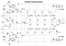
I am running the blameless/TMC on my "Big Dog" now (PB250n-below 2), and it is glorious , even at 200 watts. TMC has even allowed me to reduce biasing (cooler amp) , while maintaining phenomenal sound. 🙂
Oh , here that is to "play with" (LT)... "CX1.2U.zip"
OS
Attachments

Last edited:
Hi Jan,
Thanks. I went to the paper and liked it. Harry Dymond is a nice guy and a young, up-and-coming audio engineer.
Cheers,
Bob
Aw, shucks! Thanks for coming along, it was great to finally meet you at AES.
Thanks for that Jan.
Note that the minor loop of figure 19 is unstable.
Hi micheal. Did you simulate this? If so, how? If the minor loop is unstable, it doesn't seem to have any consequences in the amplifiers that I have built.
Also I would like to add here something that I didn't really emphasise in the paper: the optimum ratio of the capacitor sizes is exactly the reverse of that suggested by D. Self and R. Slone in their books, i.e. it's the capacitor that connects to the input stage that should be the large one, not the one that connects to the VAS collector. Note that somewhat counter-intuitively, all other things being equal, increasing the resistor value will increase the current requirement from the input stage (of course it will also change the frequency of the zero in the loop-gain function).
Also not mentioned in the paper is that of course the loop gain phase margin can be further manipulated with lead compensation in the global feedback network (i.e. by adding an RC series network in parallel with feedback resistor).
Last edited:
I'm wondering how long this symasym nonsense will be spreading here. Design fault was explained six years ago 
http://www.diyaudio.com/forums/soli...d-michael-bittner-our-mikeb-3.html#post695119
http://www.diyaudio.com/forums/soli...d-michael-bittner-our-mikeb-3.html#post695119
I'm wondering how long this symasym nonsense will be spreading here. Design fault was explained six years ago
http://www.diyaudio.com/forums/soli...d-michael-bittner-our-mikeb-3.html#post695119
The sym nonsense was rehashed with the goldmund threads .. they love it.. 😱 120K + 60K hits in a month 😱 .
I read Mike B's thread , mine is not the sym.. 😛 Most similar topologies are "flawed". Bob's version in his paper (EC mosfet amp) , is the most elegant version I've seen. Roenders folded cascode variant is quite good , too. I'm on my "3'rd round" with this design and I think the $$/sound quality ratio is better with my latest.
Carlos's simple "Blame ES" w/TMC (my BX) is ABSOLUTELY the winner in cost/simplicity/sound. It has a long term "listenability" that is hard to exceed.
Based on the standard "Blameless" with a 100uF bootstrap instead of fixed CCS , it is amazing that 7 transistors (voltage stage - BX below) can beat many of my more complicated designs. I run 1:2.2 TMC ratio (100p/220p/390R) .. freakin' beautiful !! 🙂 The only improvement to go would be a cascode to allow FET or MPSA18 LTP's (lower noise .. not that there is any now 😀 )
BTW - I am almost over my "sym fetish", ...hawkford cascodes and FET CFP LTP's are more appealing. (I'm going to try it on the cascoded circuit below)
OS
Attachments
Also not mentioned in the paper is that of course the loop gain phase margin can be further manipulated with lead compensation in the global feedback network (i.e. by adding an RC series network in parallel with feedback resistor).
One way to skin a cat (lead comp.) , better to change the ratio of TMC/TPC in conjunction with input stage degeneration to extend the margin past the unity gain point.
Only with some topologies have I had to resort to a R/C lead comp. series network.
I know many OEM's use lead comp. , I never liked it , all those dips and humps in the bode ,phase wise... the "plateau" ...with the steep slope way after UG rules.
On to the TMC ratio , at 1:1 .. a tinny sound and a bode plot showing a "hump" at 3-4mhz is observed (plot 1). At 1:2 it's just about gone and at 1:3 and up it smooths out nicely (plot 2). Also observed was less than ideal transient tests into capacitive loads with a less than stellar THD/FFT (more H3/5/7). On the real amp it was a change that could be heard , especially going from 1:1 - 1:4.
Changing the TMC resistor from 220 to 680R extends or constricts the "good" phase margin (80 degrees or more) past the UG point. One can regain any lost slew by changing LTP/VAS degeneration values.
Stuart , I have room on my next proto board for some passives , will ETMC really buy me better PSRR ?? That seems to be the only subtle improvement that can be achieved with this design. THD is licked !! 🙂
PS . Amp never outright broke out into oscillation but it DID run hotter with the sythesizers on the band speakers, (had to be a ringin' on them sawtooth and square waves
 ) (Pix 3..one of my "generators" Ha!!)
OS
Attachments
Last edited:
I'm wondering how long this symasym nonsense will be spreading here. Design fault was explained six years ago
http://www.diyaudio.com/forums/soli...d-michael-bittner-our-mikeb-3.html#post695119
Hi Dimitri
please check the link
it is dead
I am already there with the symasym topology. My version with its single pole comp. is a prime candidate for TMC (Below 1). In simulation ,I did take a hit in slew ...
Hi Ostripper
if I understood right
in my symasym
I should add ~470p cap to existing 100p cap in series and connect a resistor from the middle of the caps to negative rail
what should be resistor's value?
- Home
- Amplifiers
- Solid State
- Bob Cordell Interview: Negative Feedback