Thanx. More instances will help track it down. If you find a post with a missing attachment please report the post with comment "missing attachment"
dave
dave
Can someone provide links to the posts? Maybe we can find the missing info.
Can you provide some examples. I went thru the 1st 500 posts and then random after that and could not find any missing attachments.
dave
I see Pano beat me...
Hi Michael & Dave,
Here are a few links where clearly the graphs are missing:
http://www.diyaudio.com/forums/soli...-interview-bjt-vs-mosfet-120.html#post1207199
http://www.diyaudio.com/forums/soli...-interview-bjt-vs-mosfet-120.html#post1207201
http://www.diyaudio.com/forums/soli...-interview-bjt-vs-mosfet-120.html#post1207202
Cheers,
E.
Re; Edmond:
"This is because the induced voltage leads the current by 90 degrees and also increases with frequency. "
Ah, I had missed the voltage to current part. THX.
...........................
Don B.
Hi Don,
Here's one more link about that magic pot: http://www.diyaudio.com/forums/soli...-interview-bjt-vs-mosfet-122.html#post1207206
Cheers,
E.
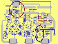
the schematic post3057 still shows Signal connected to the dirty end of the 10r resistor.
Thanks andrew , the (semi)final board does NOT reflect this(pix1). Believe me , I am listening to some pure music now. 🙂 😱
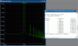
I did get this amp down to 18ppm- 1k / 75ppm- 20k (simulation-below #2). On the real amp my square wave would "ring" too much at 47pF/220pF. I knew it would come down to "trading stability for PPM's" . 🙂 Realistically , even if I used cascoded mpsa18's the noise of the input pair would most likely exceed the THD I see with this simulation.
I must try ETMC on the "test pig" next.
OS
Attachments
Analysis of Two-Pole Compensation
With agreement of the authors and the AES the paper "Analysis of Two-Pole Compensation in Linear Audio Amplifiers" by Harry Dymond and Phil Mellor is now available online:
http://dl.dropbox.com/u/13890668/Two-Pole%20Compensation%20AES%20129%20convention%20paper.pdf
thanks Harry,
jan didden
With agreement of the authors and the AES the paper "Analysis of Two-Pole Compensation in Linear Audio Amplifiers" by Harry Dymond and Phil Mellor is now available online:
http://dl.dropbox.com/u/13890668/Two-Pole%20Compensation%20AES%20129%20convention%20paper.pdf
thanks Harry,
jan didden
With agreement of the authors and the AES the paper "Analysis of Two-Pole Compensation in Linear Audio Amplifiers" by Harry Dymond and Phil Mellor is now available online:
http://dl.dropbox.com/u/13890668/Two-Pole%20Compensation%20AES%20129%20convention%20paper.pdf
thanks Harry,
jan didden
Hi Jan,
Thanks. I went to the paper and liked it. Harry Dymond is a nice guy and a young, up-and-coming audio engineer.
Cheers,
Bob
With agreement of the authors and the AES the paper "Analysis of Two-Pole Compensation in Linear Audio Amplifiers" by Harry Dymond and Phil Mellor is now available online:
http://dl.dropbox.com/u/13890668/Two-Pole Compensation AES 129 convention paper.pdf
thanks Harry,
jan didden
Thanks for that Jan.
Note that the minor loop of figure 19 is unstable.
I wrote "say 1:5". So 1:4 or 1:6 or even 1:10: will also do.
But 1:1 is far from optimal. Why? Read D.Self's article in Jan's 'bookzine'.
From my derivations there is no reason why a 1:1 ratio cant be used. I have read the article.
How to give TMC a bad reputation
Of course it can be used, but it is not optimal.
Apparently, you still don't understand that the purpose of TMC is not to reduce the slew rate, rather to reduce the distortion.
See: http://www.diyaudio.com/forums/soli...erview-negative-feedback-303.html#post2355163
Is that so? I don't get the impression. Perhaps you have only read it diagonally.
From my derivations there is no reason why a 1:1 ratio can't be used.
Of course it can be used, but it is not optimal.
Apparently, you still don't understand that the purpose of TMC is not to reduce the slew rate, rather to reduce the distortion.

See: http://www.diyaudio.com/forums/soli...erview-negative-feedback-303.html#post2355163
I have read the article.
Is that so? I don't get the impression. Perhaps you have only read it diagonally.
Of course it can be used, but it is not optimal.
Apparently, you still don't understand that the purpose of TMC is not to reduce the slew rate, rather to reduce the distortion.
See: http://www.diyaudio.com/forums/soli...erview-negative-feedback-303.html#post2355163
I did not mention slew rate anywhere in my posts. So where did you get that idea?
The ratio of 1:1 can be made optimal by the correct choice of resistor.
Of course that arrangement is intended to reduce distortion-, but it only does so for the output stage and second stage compared to double pole compensation.
It cannot reduce distortion overall to the same degree as the equivalent double pole compensator.
see:
http://www.diyaudio.com/forums/soli...terview-negative-feedback-55.html#post1160892
I did not mention slew rate anywhere in my posts. So where did you get that idea?
It was my idea. Is that a problem?
Anyhow, a 1:1 ratio slows down the SR by a factor of 2.
The ratio of 1:1 can be made optimal by the correct choice of resistor.
I don't think so, but if you think it can be done, please enlighten us.
Of course that arrangement is intended to reduce distortion-, but it only does so for the output stage and second stage compared to double pole compensation.
It cannot reduce distortion overall to the same degree as the equivalent double pole compensator.
............
We know that for years already, but who cares? Since the OPS* is by far the largest source of distortion, TMC works equally well (and sometimes even better) without the disadvantages of TPC.
* In case of class-AB or class-AB, of course. Class-heat might be a different story.
Of course that arrangement is intended to reduce distortion-, but it only does so for the output stage and second stage compared to double pole compensation.
It cannot reduce distortion overall to the same degree as the equivalent double pole compensator.
see:
http://www.diyaudio.com/forums/soli...terview-negative-feedback-55.html#post1160892
Two pole compensation allow distorsion reduction for the
vas and the output stage through increase of global NFB...
it cant reduce the first stage THD.
so what is the difference with TMC, speaking of THD?...
.....without the disadvantages of TPC.
TPC (or DPC) has no disadvantages that cannot be overcome.
Stuarts arrangement ('TMC') cannot provide better distortion performance than the equivalent double compensated arrangement because with stuart's arrangement the net loop gain about the output stage is exactly equal to that provided by DPC while the input stage 'sees' a single pole response.
This means that the input stage generates the same distortion as in the single pole compensated case, while in the DPC case it 'sees' a double pole response, i.e. more loop gain, and therefore less distortion. ie. the whole amplifier (and not just the second stage and output stage as is the case with 'TMC') enjoys more loop gain facilitated by the DPC.
Therefore all three components being equal, the distortion performance of an amplifier with double pole compensation will always be slightly superior to one with Stuart's 'TMC'.
see:
http://www.diyaudio.com/forums/soli...terview-negative-feedback-55.html#post1160803
and:
http://www.diyaudio.com/forums/soli...terview-negative-feedback-55.html#post1160892
Last edited:
Two pole compensation allow distorsion reduction for the
vas and the output stage through increase of global NFB...
it cant reduce the first stage THD.
feedback doesn't know where the distortion comes from! 😉
regards
Mike,


This topic has already been discussed ad infinitum and ad nauseum.
So, can we now return to the previous topic, i.e. the capacitor ratio, please?


This topic has already been discussed ad infinitum and ad nauseum.
So, can we now return to the previous topic, i.e. the capacitor ratio, please?
Happily, feedback does know where the signal comes from ! 😀feedback doesn't know where the distortion comes from! 😉
regards
well there is the distinction between inside and outside of the (possibly local) feedback loop(s)
distortions introduced "outside" of a feedback loop are just signal to try to accurately follow - the nonlinear input impedance of diff pair's common mode input C modulation interacting with source Z is not corrected by the global feedback in a non-inverting amp
at the same time increases in global loop gain do "linearize" the differential mode of the diff pair by requiring less diff V for the same output - using less of the input's tanh nonlinear curve
another unobvious distinction is between "voltage" and "current" gain - depending on the intra stage interface impedances and nonlinerities a modification that on one hand "increases voltage gain" (of the stage in isolation) may not increase loop T proportionately - say adding a cascode to VAS when the output has insufficient and nonlinear current gain, presenting a low impedance load to the VAS
on the TMC/DPC capacitor ratio - wouldn't TMC have different "optimum" with differing output stage gain - a "droopy" (non error corrected, Lateral?) MOSFET follower may have poor bootstraping effectiveness?
Last edited:
capacitor ratio
I repeat, can we now return to the previous topic, i.e. the capacitor ratio of TMC, please?
I repeat, can we now return to the previous topic, i.e. the capacitor ratio of TMC, please?

- Home
- Amplifiers
- Solid State
- Bob Cordell Interview: Negative Feedback


