Hartke HA5500

Hi


I need some help with this amp. I plugged in the power supply, plugged in a signal and turned the amp ON, There is power going in to the amp, but no sound. I did not hear the relay "click". I then plugged the amp thru a Variac, turned on the power switch, and starting from 240V, I slowly brought the voltage down in steps. At about 160V, the relay clicked on and there was sound as normal. At 160V AC, when I turn the amp on and off, the relay kicks in within 2 secs without any problem. If I increase the voltage back to 240V with the amp turn ON, the relay does not click off, but when I turn the amp off, plug in direct to 240V, the relay does not kick in. I have checked all the transistors and diodes on the power amp board, and they test OK. Can the problem be due to a leaking cap or transistor. Pls assist.


Thanks

bass guitar preamp with eq, what bands are best?

Hi I was going to build a simple bass guitar preamp with eq/tone shaping circuit.

QUESTION 1:
If I can only pick 4 bands, what would be the best in your opinion?
bass mid1 mid2 and treble would be the setup.

QUESTION 2:
Also I have a design I was working on with a single mid range cut, but parametric control. Because my control is a simple transistor gyrator circuit, there is a limited range. The constraints of my simple circuit are such that:
the high mid frequency range is twice that of the low mid frequency range.
i.e. I was thinking the parametric control would go from 250hz to 500hz.
or it could go from 200hz to 400hz, or from 500hz to 1000hz etc. If you could pick one range, what would range do you think would be best?

Thanks everyone for your thoughts

Restoring a Sony CDP-101 Spindle problem

Hello Guys.


I am looking for some technical help with a Sony CDP101
I am restoring this elderly machine, and have an intermittant issue with the Spindle Motor, it doesn't always start correctly.


When you insert a disc the motor turns very slowly and has trouble getting the disc up to speed, therefore no TOC read, and disc ejection.


Other times the motor spins up correctly, the machine reads the TOC, at this point when you press PLAY, one of two things happen.


1 The disc will spin up quickly, and the machine will play the disc
2 The disc is lethargic to spin up as in the problem earlier reading the TOC, the machine eventually times out and ejects the disc


It seems as though there is a "Kick Start" signal missing when the disc is lethargic to start.

I have the manual, but am struggling to determine the sequence of events during disc spin up. I have checked all other aspects and been through the alignment process, I do notice an issue during the CVLS alignment process, RV202 seems to have no effect.


Any guidance would be much appreciated,
Thanks

Pete

Neeed help with Lateral Mosfet amp

Hello everybody

I need your help in the design of the amplifier
In pdf page 17
is the schematic of the amplifier

http://www.linearsystems.com/lsdata/files/Denis Vilfort Burning Amp Slides 2019.pdf


My questions :
- Is it possible to build it with a lower supply voltage (2 * 28V)?
- with 2SK1058 / 2SJ162 transistors Renaissance?
- with transistors of the BC550 / BC560 series in LTP (or their SMD equivalents)

I tried to do simulations in LTSpice but I'm not an engineer so I don't have the proper knowledge (only by trial / error method ;-)

Thank you

Audio Injector Isolated sound card

For the first time, we feature an isolated sound card for the Raspberry Pi and other embedded systems.

It would probably be of interest to many people on this forum.

Come checkout our new project, the Isolated sound card here :
Audio Injector isolated DAC & ADC (Raspberry Pi compatible) by Flatmax Studios — Kickstarter

Hope you join the campaign. If you like the project, please share the above link with your groups/communities.

Matt

Hellloooooo first post!

Hey friends. First post here and excited to take the plunge into the rabbit hole. Planning to build an amp/preamp/integrated to drive my new Klipsch Forte III speakers that are in the mail. Heard them in the local shop while getting my TT fixed and was hooked!

What amp kit do I want? Lots of recommendations for tubes with horn speakers, most often suggestion being Bob Latino ST70. Have not looked into ANY solid state kits. Having a volume remote and tone controls would be cool but not a deal breaker.

Only have two sources, a Denon DP300 TT (built in preamp) and streaming sources (currently Apply Music via AirPlay, maybe Tidal, so either an Apply Airport Express or Bluesound Node). Musical interest runs the gamut from rock of all decades, soul, reggae, funk, country but also jazz and occasional classical. I’m a bass player so bass control/response is important to me.

Happy Sparkler S504 owner


Dear Victor,

I wanted to write to let you know how pleased I am with my new Sparkler DAC (S504 Unison). I love the sound! It really makes my jazz and classical music collection come alive. Everything has a much fuller, richer sound versus the previous DAC I had been using. Some other reviewers have called it a “musical” sound and I agree – everything sounds much more lively with this DAC. I attended a live classical music concert yesterday and enjoyed the immediacy of the sound. This was what I had been missing with my previous DAC.

Besides the sound, the Sparkler S504 Unison DAC just looks cool. The handmade gold colored Japanese paper is quite distinctive. This DAC is very much a unique, handmade object, so rare in this age of mass production. I could have spent a lot more money on a so-called “prestige” brand DAC, but honestly this is much better – how many people have a Sparkler DAC?

I also ordered a full set of Sparkler interconnects, plus speaker wiring and a USB to SPDIF converter. All seem very well made and reasonably priced, and work great. Despite being custom made, the Sparkler products are priced well below other supposedly affordable brands.

I love that Mr. Tsukahara is basically running a one man shop, doing all the design and production by hand. He should be commended for his efforts.

And thank you for supporting him!

Best regards,

Jaylat


Vicor DC-DC for B+

I have enough spare parts to make a PSU for a Salas 6V6 preamp. The idea is to run it from a 24V DC power supply.

I have several of these:
VI-J1B-EY | VI-J00 Series DC-DC Converters | Vicor
and a few others, enough to make a 330VDC B+ from a 24V PSU. The idea is to put the converters in series to get the necessary voltage. I might put this on the final B+ output: 21st Century Maida Regulator: A modern B+ voltage regulator – Neurochrome

I also have this, that I can trim to 6.3 for the heater.
VI-J1T-CY | VI-J00 Series DC-DC Converters | Vicor

I plan to use this ripple attenuator, which I also have, on the output of 6.3V converter.
Ripple Attenuator Module - RAM | Vicor Corporation

Besides the fact that this is all unnecessarily complicated, I'd like to try it. Are there any reasons not to? How about at amp startup? As I understand it, this might be a difficult scenario for the PSU.

Can I put an NTC on the output of the 24VDC power supply, and before the converters?
https://www.alliedelec.com/m/d/5537bfe04244704ae50832ab5bfb2832.pdf

  • Poll Poll
Open source speaker project - Part II

Design Goal

  • Classic -Amp Friendly- Hi Sensitivity (92db+), Higher Bass Ext (f3 40-45Hz), Cabinet Size 60-80

    Votes: 18 17.8%
  • Classic -Bass Friendly- Deep Bass (f3 35-40Hz), Lower Sensitivity (88db+), Cabinet Size 80-110

    Votes: 10 9.9%
  • Classic XL -Amp and Bass Friendly- Hi Sensitivity (92db+), Deep Bass (f3 35-40Hz), Cabinet size 100+

    Votes: 12 11.9%
  • Tower -Amp Friendly- Hi Sensitivity (92db+), Higher Bass Ext (f3 40-45Hz), Cabinet Size 60-80

    Votes: 13 12.9%
  • Tower -Bass Friendly- Deep Bass (f3 35-40Hz), Lower Sensitivity (88db+) , Cabinet Size 80-110

    Votes: 21 20.8%
  • Tower XL -Amp and Bass Friendly- Hi Sensitivity (92db+), Deep Bass (f3 35-40Hz), Cabinet size 100+

    Votes: 27 26.7%

Ok, Here we will continue from where we left off from previous thread - Open source speaker project?.
First poll result was for a 3 way classic speaker (no horn), the budget is 500-1000$ for drivers only (excluding the crossover parts and cabinet).

EDIT 9-20-18 :
Tower XL discussions and development will be continued here :
Open Source "Tower XL"

Attachments

  • first poll.JPG
    first poll.JPG
    98.8 KB · Views: 1,717

Designing new cabinets, what do you think?

Hello,

I'm designing new cabinets and I thought it would be nice to keep the baffle surface around the tweeter and midrange as small as possible to give the ultimate openness, airyness (?) and soundstage.
I came up with this, the tweeter and midramge are in a very small sort of bookshelf on top of the bass cabinet. This is very small. Though, the bass cabinet is like a wall, this will only cause worse reflections. What do you think. Line that wall of the bass cabinet with sound dampening and will it be very good or will it be better of with just a normal large baffle?

Attachments

  • 20200124_143516.jpg
    20200124_143516.jpg
    987.5 KB · Views: 604

help hacking harman

I am gutting an HK550vxi for the amp. I have successfully removed tone, volume,balance,rec,tuner,phono RIAA and RCAs and rewired it to a single RCA input. Sounds great, now I am building a new enclosure, changing the speaker terminals and power switch. The new enclosure is mostly made of wood, the only metal in it is the 1" amp riser and the back panel. The amp board currently has a ground to the metal chassis, can I connect this to the amp riser and back panel and call it good? I could also make a small chassis to contain the transfo, ac power input and inputs outputs but that would be harder and it takes away from the fast and dirty hack aspect....When this one is done I have a Denon AVR3300 with a 5 channels at 105W/8ohms that I need to gut

Thanks

Panasonic SA-XR55 Digital Amplifier

Panasonic SA-XR55 9 Channel amp - one channel not working...

I always loved how these Panny pure Digital amps sounded...this one was on basement HT duty for a while until I decided I needed a HT Receiver that was able to switch HDMI (this does not have HDMI)..still a fantastic sounding amp when connected to digital source...

Anyway, hows $75 + ship or pick up West Sub of Chicago?

Attachments

  • 1.jpg
    1.jpg
    990.1 KB · Views: 200
  • 2.jpg
    2.jpg
    997.3 KB · Views: 206

Help Please on my Amp build

Can any of you audiophiles help me with this question ? can a Tube Preamp enhance an A/B Amp . I've read conflicting info on this subject on the web with authors saying high end boutique amps use this set up. But after watching a Bob Carver video he explains how a tube Amp works with it accepting return power to the tube by reflection of the driver and an A/B cancels this effect. So I'm confused now thinking maybe a tube preamp would be a waist of money.🙁http://https://www.youtube.com/watch?v=LQ9USqpclWc
The amp boards are 4- Yuan-Jing 3 x TDA7293 Parallel 250W Mono Power Amp Board .
Any help would be greatly appreciated....

Attachments

  • DSCN1067.jpg
    DSCN1067.jpg
    1 MB · Views: 428

Recommend a 2 or 3 way project for 80hz and up

After making full range floor standers and a pair of subs I want my next project to be a 2 or 3 way. I’m trying to get to a higher degree of realism at higher SPLs than 6” full range can do. I only need low end above 80hz (or maybe as high as 100) so I’d like to maintain a modest efficiency (say, above 90db/W) without a huge box. Listening distance is typically 8-10ft when on the couch, the room is 16x32’ with cathedral ceilings.

I’ve been looking a at a couple of Troel’s Designs, specifically the Quattro MKII and the SBA 16 MTM. At my most adventurous his Faital 3 way seems doable but frankly is a bit bigger than I’d like right now. I love the look of big speakers but I’m short on tools and workshop space to manage big cuts and parts.

So I’ve been poking around the web for weeks and I’m hoping a little input from the forum will help me find any other options that fit and ultimately pick something to work on soon.

Thanks

FS: CX-301 globe and RCA 6l6gc

Hi all.

Next up:
a pair of boxed (but not identical glass) RCA 6l6GC. I think these are NOS, but not certain. These are also sought-after black plate (see pics). Both test strong on a calibrated I-177 tester (4600 and 5300 micro mhos). $175 USD for the pair.

Next are 6 X cx-301 globe (01a equivalent). My Gm measurements are (1000, 1100, 1200, 1200, 1300 and 1400). All are strong and were purchased from a reputable dealer and never used. I always saved them and used ST envelopes, but now don't have the 01a preamp anymore. $150 USD for the set of 6.

I'm shipping from NZ.

If you have a lot of posts on diyaudio, I'm happy to guarantee them. If you don't, I won't guarantee.

If you have helped me out on any of my posts in the past, send me a PM and I'll hook you up with a sweet deal.

You pay shipping and PayPal fees.

Next up will be a heap of Russian valves including 4p1l.

Please see my other auctions for a bunch of 45 triodes.

Thanks for the community guys.

Attachments

  • 01a_lineup.jpg
    01a_lineup.jpg
    437 KB · Views: 227
  • 6l6gc.jpg
    6l6gc.jpg
    768.7 KB · Views: 234
  • 6l6gc_box.jpg
    6l6gc_box.jpg
    328.9 KB · Views: 222

Purifi PTT6.5W04 or Wavecor WF182BD10 or Seas H1215

Hi

New to DIY and wanting to make a Awesome Top Level sounding 2 way BS pair

Was reading on great reviews on Purifi Drivers but not much work done out yet since its new. Its expensive and was looking at a good option to Purifi will the
Wavecor WF182BD10 woofer/ SEAS H1215-08/ SEAS H1224-08 be able to compete with the Purifi if someone can throw some light on. I do not wish to use a 3 way or add a subwoofer. Desire is to have the best 2 way Bookshelf room size is 14x20ft

Would like to go Active with miniDSP and Hypex or ICE class D amps.

Do not want to go the passive route.

regards
Rajeev S

First Class D Amplifier Design - Your Opinion?

Hello guys!

Lately, I've been working intensively on Class D amplifiers.

Now, I have developed the following circuit and wanted to know what you think about it.
For example, I am not sure if I designed the negative feedback correctly.

Unfortunately, I cannot simulate the entire amplifier because I have not found any Spice models for the LM5104 and Si8610BB. I am using LTSpice, Multisim and Tina TI.

Important: R21, R32 and R34 are 0R jumpers and are for test purposes only.
At the end, R21 and R34 remain empty.

Thank you for your answers!

Best regards

Simi
si1505do@gmail.com
DIY Electronic Projects

Attachments

Dynaco MK III P782 power transformer issue.

I have redone a pair of those MK3 to original with tube rectifier,etc.

I just got a power transformer issue, primary is short. Secondaries are all ok.
It does not smell burning, i did open it could not reach inside the primary section as mostly have to destruct it completely.
Anyway, P782 dates maybe from 40years++
I was in a Paoli design modded MK 3 amps I bought used.
I highly suspect that, because of this Paoli design that used a SS rectifier and a 1000uF capacitance, it did fatigue the power transformer all right .
This Paoli mod was supposed to be great, but I now don't belive it, and if a product or item is design for a typical service, please , let it be the same.
Just to advise community here.
Will replace both P782 soon, well it happens..........

Modifying Diamond 9.6 crossovers

So I'm wanting to try bi-amping, but of course there are already passive crossovers in my speakers, and I understand I'll have to remove/replace, or at least modify these before I can make the most of bi-amping with an active (or software, at first) crossover.

The speakers have 'bi-wiring' binding posts, with the +high and +low, -high and -low paralleled by plates. I've traced the two crossovers out, in ignorant noob style as you can see 🙂 I'm hoping somebody can help me identify the topology so I can determine where I need to cut a trace, add jumpers etc to disable the filters an active cross will provide.

I'm hoping there'll be a way of just skipping the first filter of each unit, drilling a hole and moving those input wires.

I'm not able (easily) to measure the inductance of those big coils, but if it's required knowledge, then I'll find a way 😛 I can tell you however that the mid/bass crosses at 150Hz, the mid/high starts at 1k, and crosses to the tweeter at 6k.

Cheers for your time, to anyone reading the thread ;P

Attachments

  • cross_H.jpg
    cross_H.jpg
    134.4 KB · Views: 894
  • cross_L.jpg
    cross_L.jpg
    141.8 KB · Views: 868
  • schem_H.jpg
    schem_H.jpg
    46 KB · Views: 925
  • schem_L.jpg
    schem_L.jpg
    33.4 KB · Views: 819

There is no place to park planes?

You know, because of the (well-founded) fear of contracting COVID-19, planes around the world are flying without passengers. Needlessly spending millions of liters of fuel and polluting the atmosphere, etc. etc.
This, the news says, is because if they don't, airlines will lose assigned routes.
This is a difficult thing to accept. Is a temporary suspension of said regulation so complicated to implement?

It seems that there is not enough place in airports to park so many planes that are constantly in flight, in an established routine, that cannot be interrupted, and nobody could have foreseen the advance of COVID-19!
It seems logical, if we also think that the available parking spaces are already occupied by many 737 Max out of service.


Is that so?


Experience

Single rail psu 2 rows of caps

Probably too late to ask seeing as I've spent some time today building this!

I have soldered up the cap bank for a 51Vdc supply for a tpa3255. Used 14 of 2200uF caps and for packaging purposes I have 2 rows of caps.

These are all aligned ground inwards, so the two inner copper wires are ground. One outer wire will be in from the bridge rectifier and the other outer will be the smoothed supply.

Have I made a potential ground loop with the physical looping of the wire around the caps.?

Attachments

  • 20200317_184728.jpg
    20200317_184728.jpg
    754.7 KB · Views: 127
  • 20200317_184722.jpg
    20200317_184722.jpg
    776.5 KB · Views: 135

Questions About Impedance

I have a set of Polk S20 speakers that were dropped and now sound like crap. I'm in the process of replacing the drivers in them.
The specs from Polk's website state that these are 8 ohm speakers, yet when I measure the voice coil of the woofer with my meter I get a reading of 3.56 ohms, which is typical of a 4 ohm woofer.

Why is this?? I understand that an 8 ohm speaker will read less than 8 ohms DC resistance but it shouldn't be this low. So now I am wondering if I need 4 ohm drivers. Confusion!!

MDD technology in multi-way systems

Hello to all
in the "MDD Multi Delays Diffraction (Multi TL, omnidirectional, single drive, ...)" tread I inserted a post on the MDDXH135 prototype. It has an omnidirectional MDDFL front loading for high frequencies, very simple to make, and an MDDBL rear loading for low frequencies that requires more work. I will continue to insert the new posts in the "MDD Multi Delays Diffraction (Multi TL, omnidirectional, single drive, ...)" tread.

Acoustic loading systems can also be used in 2- and 3-way systems.

The MDDFL front loading makes omnidirectional the emission at medium and high frequencies for any electrodynamic speaker.

MDDBL rear loading can be applied to the woofer. It has 12 transmission lines with 12 resonant frequencies distributed over an octave, effectively making its behavior neutral in the frequency domain. See neutral cabinet page.

For those who want more information on the MDD technology that led me to develop these acoustic loads, I recommend the acoustic page.

Right now I don't have the material or the skills to make quality Multi-Way systems. I am available to give more information about my prototypes for experiments in Multi-Way systems.

Thanks for your attention
Claudio


MDD3FE25 an MDD project with the 3FE25 driver
https://www.diyaudio.com/forums/pla...nidirectional-single-drive-8.html#post6170069
other documentation is published at MDD3FE25.

Attachments

  • mddhx135-06.jpg
    mddhx135-06.jpg
    178.9 KB · Views: 114

FS: UTC CG-101 Vintage Swinging Choke

For sale here is a vintage UTC CG-101 swinging choke. This is rated for 150ma. and has a dcr of 110 ohm. 5-25hy operating current. This would be great for a choke input power supply for a EL84 PP amp or something similar.

$75 plus shipping. Paypal friends and family please. Shipping is from Vienna, Austria.

Thanks!

Attachments

  • IMG_6853.jpg
    IMG_6853.jpg
    368 KB · Views: 169
  • IMG_6854.jpg
    IMG_6854.jpg
    766.8 KB · Views: 160
  • IMG_6855.jpg
    IMG_6855.jpg
    631.6 KB · Views: 154
  • IMG_6856.jpg
    IMG_6856.jpg
    389.3 KB · Views: 145

Peavey studio pro 112 loud popping when you turn if off

Hi ya guys
I have a peavey studio pro 112 amp. It has recently started giving out a very loud popping sound when it's turned off.....its just like it's on full volume ,it's so loud..
What I've tested
No instruments connected
All controls set to zero
Different speaker
The noise is still there, does anyone have any ideas, as my local music shop have told me all amps do this ?
IT NEVER DID BEFORE !
Amy help appreciated

HELP - Efficient Enclosure for Mutant MT1207 12" Subwoofer

Hey all, I have a Mutant MT1207 800w 12" car subwoofer which is in very good condition but lacking an enclosure. I've looked around quite a bit and haven't managed to dig up any of the T/S parameters, just a few conflicting spec sheets regarding the MT1210, which seems to be my subwoofer's big brother.

What I need in my enclosure is efficient bass. From the research I've done, it seems like either a tapped horn or possibly a HOG scoop would be what I'm after, but all the plans I've found are for larger Sd drivers. A 6th or even 8th order bandpass could also be an option, but from what I've read these seem to rely more critically on the correct T/S specs. (maybe that's a false assumption?)

Space is not really a huge constraint, I have about a 1m x 1m x 600mm area, which happens to be in the corner of a small-ish room.

Any and all help would be really appreciated! Thanks!

Epson projector ballasy bypass

Good morning. I have a problem with two epson projectors. One is EB-825 and the other is EB-85H. After disassembling them the only difference I have found is that the second one has a less powerful lamp and the epson brand ballast besides that it does not have a temperature sensor in the ballast, the first one has the tdk brand ballast. I need to remove the ballast to put a led light on. The problem is that these projectors are not worth jumping the ballast that is upside down, but they communicate through a serial port. I have found very interesting things in this forum Прошу помощи! Создание эмулятора балласта лампы проектора Epson. (Страница 5) / Аппаратные вопросы / Форум arduino.ua the problem is that it does not have the same protocol as mine. After downloading the program to the arduino nano and connecting it, there are times when a signal comes in from the projector but the arduino doesn't respond at all because it doesn't recognize it. The problem is that I do not have an original lamp to put it to be able to read the codes that I should answer. I hope someone can help me.
Thanks in advance.

SONY TA-E1 preamplifier clone

Hi

I need help with a prototype development. Do I need to change something on schematic or pcb?

Schematic is from Sony TA-E1 preamplifier. Sony is made with SMD parts, my version is with TH parts.

I have LTspice simulation(TAE1-ccsbip.asc), and if someone can help I would be very thankful.

Attachments

Salas mini-Reflektors + DC Flexy

For sale two mini Reflektor regulators along with DC Flexy from you know who. Parts from GB, additionally the DC Flexy comes with 22,000uf 40V Philips capacitor (enough to power both Minis) and LQA06T300 super fast rectifier diodes.

Edit: and of course the are in perfect working condition as they should be, currently with 5VDC output.

I'll provide additonal leds (green, red and yellow) for voltage setup and additional Dale resistors for current setup

SOLD

Attachments

  • mini_1.JPG
    mini_1.JPG
    698.8 KB · Views: 414
  • mini_2.JPG
    mini_2.JPG
    614.3 KB · Views: 422

FS Soekris DAC 1021-02 with input board

For sale Soekris dam 1021-02 with Nurmunds input board for spdif, optical, usb input and rpi board input.
Dac is modified with almost all mods that are suggested:
Transistor mod, capacitor mod, disable opamp output stage, just raw output is for use. Optimized power supply, 2x5v Kubota preregulator for shift levels, and lt1085 5v preregulator followed by 3,3V lt3042 and TPS7a4501 for fast transient 1.2V lines.
Dac is completed and perfectly working, just add 2x6-9V transformer for +-5V kubota regulator and 2x6v transformer for other 2 lines.

Boards:
Soekris dam 1021-02%
Nurmundss input board with input selector
Diyinhk usb board
Power supply board with Kubota and 2 other preregulators

All together for 200€ plus shipping....FREE GIFT RASPBERRY PI!!!

Attachments

  • dac total.jpg
    dac total.jpg
    283.1 KB · Views: 312
  • dac2.jpg
    dac2.jpg
    301.8 KB · Views: 309
  • input board.jpg
    input board.jpg
    308.1 KB · Views: 311
  • soekris board.jpg
    soekris board.jpg
    517.7 KB · Views: 319
  • xmos.jpg
    xmos.jpg
    233.2 KB · Views: 306

A geometry-based grid-dip meter emulation

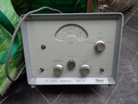
The traditional grid-dip meter is an old favorite of the DIY/Ham community: initially, it was a tube-based instrument, but in the sixties it has been modernized with FETs or BJTs whilst retaining the same basic operating principles.

It is a variable-frequency oscillator using a number of pluggable coils and a variable capacitor to cover the frequency range, typically ~200kHz to 100MHz.

The coil is external and can be coupled to a tuned circuit to be tested.
The grid/gate/base of the oscillator has its bias connected to a galvanometer: the oscillation combined with the grid or base rectification generates a current dependent on the activity of the oscillator.

Typically, the bias is adjusted to be on the verge of oscillation, and the frequency is varied with the coil lightly coupled to the resonant circuit under test. When the frequency of the oscillator coincides with that of the tuned circuit, a significant amount of energy is siphoned by the external circuit, leading to a sudden dip in the amplitude of the oscillations.
This dip shows on the galvanometer, and by reading the calibrated frequency dial, it is possible to know the tuning frequency with a reasonable accuracy.

The measurement process is slow and not very deterministic, but the instrument is cheap, and can have other uses, like a frequency generator, which is why it was popular for a very long time.

The alternative I propose emulates the main function of a grid-dip (determination of the resonant frequency), but uses totally (if not opposite) principles: the circuit does not oscillate until it is presented with a tuned circuit.

The circuitry of the pseudo-grid dip is essentially aperiodic, meaning it works for all frequencies without coil change or manual tuning: as soon as a tuned circuit is presented, it oscillates at its resonant frequency.

How does it work?

The oscillator is amplifier-based, and conditional on the external tuned circuit.
"Canonical" oscillators like those used in grid-dips are based on a 3-terminal active device (tube, FET, BJT, etc.) and three reactive elements: two capacitors and one inductor results in a Colpitts configuration, and two inductors and one capacitor a Hartley.
Other types of oscillator are based on a quadripole and a frequency-selective network: a typical example is the diff-amp oscillator.
This circuit is quadripole-based, but the selective network is external and also acts as a gate: in its absence, the positive feedback is completely absent.
In addition, the external circuit is only inductively coupled, to mimic the original instrument

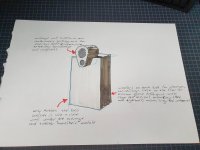
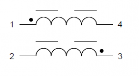
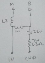
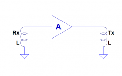
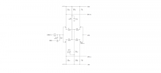
This sketch outlines the electrical configuration:

attachment.php


Nothing is particularly unusual: it is an amplifier looped back on itself, except the positive feedback is nonexistent, because the input and output inductors are not coupled.
Thus, such a circuit has no chance to oscillate, but then, where is the catch?

The answer is in the geometric configuration of the coils: they are magnetically orthogonal, meaning their coupling coefficient is zero.

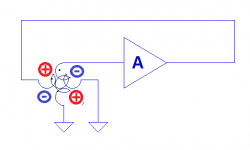
This is a more faithful representation of the physical configuration:

attachment.php


It is now obvious that no coupling can exist between the Tx and Rx coils, but how can such a configuration oscillate in the end?

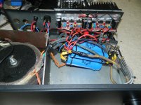
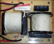
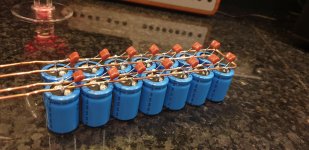
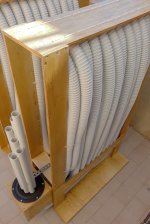
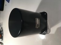
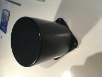
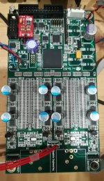
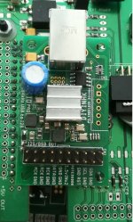
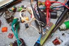
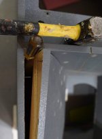
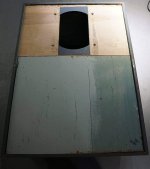
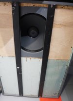
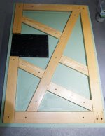
The two coils divide the space into 4 quadrants: a picture of the prototype should make things clearer:

attachment.php


The two coils of this prototype are ring-shaped, about 27mm dia, and comprise 6 turns of wire-wrapping wire. Their inductance is a little under 2µH.
If a tuned circuit is present in any of the quadrants, it will be able to interact with both inductors, because it will not be orthogonal.
The transmission coil can induce a resonance in the tuned circuit, and in turn, the current in its inductor will couple to the reception coil.
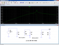
This is shown in this simulation:

attachment.php


Coupling coefficients are only defined for L1/L2 and L2/L3, yet the signal from L1 manages to reach L3.

To summarize, the Tx and Rx coils do not see each other directly, but the Tx coil can “illuminate” the tuned circuit, which then becomes visible to the reception coil.

Attachments

  • EmuGrDip.png
    EmuGrDip.png
    3.5 KB · Views: 1,358
  • EmuGrDip1.png
    EmuGrDip1.png
    4.4 KB · Views: 1,304
  • EmuGrDip2.png
    EmuGrDip2.png
    64.4 KB · Views: 1,565
  • EmuGrDip3.jpg
    EmuGrDip3.jpg
    535.5 KB · Views: 1,291

Akai M8 rebuild up and running!

My amps in the Akai M8 chassis are working. I have started a few threads about it, but I wanted to show the finished unit. I completely stripped out the stock circuit. The chassis and stock iron now hold a 12B4 preamp followed by an RH84 (SE partial feedback 12AT7/EL84 design). This amp will soon drive the tops of a biamped open baffle setup. The 12B4 stage will also drive a mini DSP which will be used to crossover to and EQ the woofers (and a subwoofer later!).

I reused the the stock transformers and choke. I also used the current 30K pot in front of the RH84, and the original speed switch on the back of the pot switches to a little cap that will roll off the fullrangers (that may or may not be the full crossover). I swapped the 1/4" jacks for RCA's. Two inputs, a toggle switch, and pre-out jacks. I drilled out the holes for the original output jacks to install fuse holders. I used to stock sockets, though I did remove one and shift another on the channel that had the 6AR5 (hated the idea of the mono's looking different). I'm using the rectifier filament winding for the 12B4. I added a couple of dropping resistors, as the filament voltage was a little higher than ideal. I put a law faked linear PEC pot in front of each pre (500K pots with 33K resistors). I know it looks a little sloppy. I'm not used to laying things out on that sort of strip, and the additions to the pre section weren't factored in to the original plan.

To make it possible with the stock power transformers, I used SS rectification. The B+ on the EL84's is just over 300V (perfect for the RH84). The power transformer stays plenty cool, but I don't have the meter lamp (or meter) connected. I'm using a moderate sized first cap (22uf Nichicon), a giant RIFA second cap (330uf), a 5uf motor run on the 'T7 and a 33uf THSA for the 12B4. Actually, as part of sorting out the pre, I added another RC section, so there is another 22uf in there as well. A la Poinz (and others), I put a couple of 1uf caps across the filament windings. I've also got a couple of 600V film caps across the diodes, and I'm taking the B+ from the CT of transformer.

The RH84 section is built according to the schematic with basic parts. The 12B4 was more of a challenge. It was initially a little unstable (motorboating). An extra RC section didn't help, nor did changing the plate load resistor for a CCS (stacked mosfets). Using a smaller coupling cap eliminated it, but that couldn't be a permanent solution. LED bias finally did the trick. I've currently got 6 ultra bright green LED's per tube. If memory serves (I've been out of town for a few weeks), that's about 15V. The CCS is set at 17ma.

It sounds nice after only a few hours. It is plenty quiet, though the power transformers do make a little mechanical noise (as nearly all seem to on my audio circuit. It drives me nuts). A big improvement over the stock Akai circuit! Compared to my other tube amp (a variant of Eli D's El Cheapo), it fits many of the SE stereotypes. The midrange is lovely. The bass is a bit warm and soft, but my EC has a big iron advantage. This amp won't be used below 150hz anyway. The high treble seems a little polite, but it might open up. Still, what a midrange!

Overall, I'm very happy. I have very little $$ invested in this build, but stripping the original parts out and getting the pre stable did take much longer than I anticipated. Pick up an M8 if you want a fun little project. My wife even likes the look! They are easy to recap, and you may even like them stock. If not, you can do something like this. A phono stage could easily take the place of my 12B4 stage, and it would be easier on the power transformer.

Hopefully I'll soon have the whole system running.

Paul
Wild Burro Audio Labs - DIY Full Range Speakers

Attachments

  • Front.jpg
    Front.jpg
    63.2 KB · Views: 693
  • Back.jpg
    Back.jpg
    54.2 KB · Views: 674
  • Bottom.jpg
    Bottom.jpg
    62.6 KB · Views: 667

Replacing whizzer with phase plug or dust cap

Hi,

I am assuming that fullrange drivers like Visaton BG20 with whizzers dont provide uniform polars. A whizzer ends up producing highs mostly on axis at the expense of spoiling the off axis response. This is an acoustic problem so cant be solved by EQ either.

Drivers like TC9 etc have a dustcap and their on axis and off axis response are uniform.

See 4&5 for visaton TC9(dustcap) and Visaton (whizzer) comparison below
Radiation patterns of full range drivers

Can whizzers be improved to yield better polars?
Does replacing whizzer with dustcap improve the polars?

Thanks and Regards,
WA

McIntosh speakers help

I have some McIntosh speakers pictured below. Need to know the specs for them and can’t find anything online. Originally were in Ford GT. The original model of maybe 15 years ago or so. Does anybody have any info on these?

The intent is to use them in a portable stereo build. I wanted to know some parameters in order to make ported enclosures. Is there any way of making a ported enclosure sound semi-decent without knowing the T/S parameters?

[/ATTACH]

Attachments

  • 482E807D-748C-482B-BEEE-D1B5B77B3307.jpg
    482E807D-748C-482B-BEEE-D1B5B77B3307.jpg
    888 KB · Views: 94

Yet another Pensil 10p build

Hello everyone!
This is actually my first post here despite being a member for almost 10 years!

I also finally decided to pursue my first-ever speaker build, having at last decided to go for the Pensil based on the Markaudio Alpair 10p.

I have decided to use 18mm birch plywood, but I'm currently wondering about this: Since the material is roughly 1mm thinner than the material used in the plans i wanted to account for this, but should i prioritize to get the internal dimensions exactly right or should I instead make sure the baffle has exactly the right width? If I just make sure the internal dimensions are right the baffle will be roughly 2mm narrower than the drawings, maybe this is negligible?

I'm thankful for any input, and I'm sure more questions will pop up along the way!

BR Anton

Technics SU-CO4

Hi !


I'm very new to technical stuff like this, but seeing the actual epidemic quarantine in my country I've got time to try to solve that kind of problem !


So I've got a Technics intergrated amplifier SU-C04 since 5 years. It has been working really well all this time. And yesterday, as I was preparing myself to spend a month home alone because of the virus, it just stopped working. When I push the start button, the light doesn't turn on and the sound neither.

I tried to open it and clean the dust inside but it doesn't change anything.

Any advice ?

Thank you very much


Etienne

Complementary LTP transistor matching

I am trying to build the Krell KSA-50. Here's the schematic of the input stage.
I couldn't manage (2N6431/2N6433) complementary pairs but instead I bought some (BC337/BC327) complementary pairs, hoping to finish the project. As far as I know, the 'hfe' of the transistors in the input stage of an amplifier need to be matched.
I bought around 2 dozens of each transistors but the 'hfe' of the NPN is not matching exactly with that of the PNP's. The closest match for 'hfe' I got was '265' for NPN and '242' for PNP's. I know there is a risk of DC offset at the output if the gain 'beta' of the transistors are not matched.
Now, if I build this amp with the transistors that I got, how much offset should I
expect at the output? Is there a limit in how much the 'hfe' can vary? Also, is there any other way like shifting (collector and emitter) resistor values to minimize the DC offset?

Please help. I am making this project on a protoboard and it will be difficult to solder or desolder the parts. I am asking this because if there is a maximum risk of the amplifier not being able to work properly, I won't build the project. Thnx everyone in advance!!!!

Attachments

  • XXXXD.png
    XXXXD.png
    26.7 KB · Views: 523

Recommend class D amp to replace damaged Dual CV60 board

I got Dual CV60 for spare parts. Its power amp stage is physically damaged. However the rest is cosmetically in perfect condition. I have been thinking of using its preamp with controls and case and feed it into class D amp.
I have been using 2x50W amp like this for years and it sounds really good with my system.
Mini Class D Power Amplifier HiFi Stereo 2.0 Channel Digital Audio Amp 50W+50W | eBay

Now I have got tired with all the separate parts(Phono pre, switch box, tone control, power supplies) and accompanying cables and think to put everythin inside one box.
This Dual has very good dual rail power supply of +/-15V that could feed my DIY Phono pre as well.
So can you recommend a board that can use the Dual power and sound good according to your experience? I think that 50W per channel is plenty - I haven't got past 4 notches(out of 10) on Volume knob ever.

Need your expert advice

While searching for low power car amps I found this one and since I did not find any review video of this one.

I was wondering if anyone could give there opinon on this amp as the seller claims that it has exceptional sound.

AZDOME X9 Plus DSP Amplifier Bluetooth 5.1 channel 31 band EQ tuning audio processing amplifier stereo subwoofers car audio|Multichannel Amplifiers| | - AliExpress

Enter: Voice of the Futon [Dehorning the Altec 828]

Genesis began as "'horn removal' or: deconstructing an A5/A7/828? " on the AUB.
'horn removal' or: deconstructing an A5/A7/828?

Simply put, You can get close, but no it's not practically possible to save both the horn flare and the cabinet.

Advantage: Cabinet

The 828's top and sides are 5/8" paperboard, and so once gutted they are not very good except to me as square starting point with ok enough cosmetics.

So we concentrated on salvaging the baffle (I barely do straight lines, let alone new circles) to mount a GPA 416-8C in a reasonably rigid ~12 ft3 ish sealed box - for about half the 416 spec'd Vas (iirc).

enter: Voice of the Futon MKI

- Innards were gutted save for the corner blocks left in place.
- slanted horn board removal leaves dado'd slots visible in the front, these are filled.
- existing front face was reinforced, extended with wood support pieces salvaged from a futon. This makes a continuous seat for the full-length removable front baffle.
- Top and Bottom are reinforced with 3/4 ply (good stuff), sides are 3/4 (probably flooring ply). Having left the corner blocks intact forced cutting these into jigsaw shapes: boo.
All additions screwed (probably too many) and glued with generous application of PL Premium, such that we're probably approaching constrained layer dampening of a sort.

- rear panel seat was given an additional insert step (pine) for better sealing, better rear panel screw bite.
- rear panel (not paperboard) 2x4 is removed (paucity of glue, popped right off!) and was glued and screwed with the nicer (some sort of hardwood) pre-finished pieces from the futon

The front panel/baffle is mocked up, i.e. screwed but not glued yet, as I want to leave it open for modification or revision for now. Front panel screw pattern matches the rear for interchangeability.

Finally, steel from victim futon #2 was added to the exterior face of the front panel for rigidity and reinforcement. Attached from the rear, it joins the baffle with the filler panel.

Unfortunately, I've not yet been able to remove the baffle without some unsightly damage to the exterior face. along the top edge. And note that the opening is offset. This forces orientation as seen for woofer clearance with the cabinet's panel seat.

The paint scheme is 'Accidental Mondrian'.


Next up... Voice of the Futon MKII with EF styling package!

Attachments

  • P01_DSC03506_30p.jpg
    P01_DSC03506_30p.jpg
    138.9 KB · Views: 297
  • P02_DSC03182_30p.jpg
    P02_DSC03182_30p.jpg
    136.1 KB · Views: 296
  • P03_DSC03301_30p.jpg
    P03_DSC03301_30p.jpg
    154.5 KB · Views: 298
  • P04_DSC03294_30p.jpg
    P04_DSC03294_30p.jpg
    116.4 KB · Views: 315
  • P05_DSC04212_p30.jpg
    P05_DSC04212_p30.jpg
    198.7 KB · Views: 301
  • P06_DSC03250_p30.jpg
    P06_DSC03250_p30.jpg
    187.5 KB · Views: 125
  • P07_DSC03309_p30.jpg
    P07_DSC03309_p30.jpg
    231.1 KB · Views: 119

Creating a DIY DSP “server” that can apply FIR filters to all incoming sounds?

Hi Guys,

I was wondering if there were any examples or literature of DIYers creating their own headless DSP PC. I am building a 2 way speaker and want to implement a digital XO on it.

Has anyone created a small PC whose only job is to act like a Digital XO and apply DSP and FIR filters to all sounds coming to it? Should this XO PC run Linux or Windows? Can this XO PC be connected to a normal work PC, MacBook and receive all sounds from them, like YouTube, Foobar, Video Games etc?

Possible Chain: Windows PC/MacBook to DSP XO PC to 4 Channel DAC to 4 Amp Modules to Tweeters and Woofers

I’ve been reading a lot of great work done in the past few years by some genius members of this community, hoping someone can point me to some data to help me out.

Thanks for your time!

JBL Bp1200.1 Psu driver transistors

I'm repairing this amp and the psu driver transistors are blown the original instaled was a1266,(the service manual saids a1268 for the PSU driver transistors) what do you think about replace this with a1023?..... I have in hand a1023 , if this is not a good idea i could order a1266.
I asked about this because i have repaired another class d amps and some of them use in their psu a1023 transistors as transistor drivers.
Thank you

How far away is the horizon in a high altitude spyplane?

Member 6L6 and I were amusing ourselves listening to the SR71 "Los Angeles Speed Check" audiotape, when I realized that a teeny fragment of it sounded, to me anyway, just a little questionable.

The SR71 pilot casually says he was directly over Tucson AZ and could see the skyline of Los Angeles CA out the window. Which seemed, um, improbable.

So I hired an 11th grader to work out the trigonometry of the situation, and make a plot of (distance to the horizon) versus (flying altitude). Result is below.

To my surprise, Google Maps says there are 484 miles of Interstate road (which is certainly NOT a perfect straight line) from Tucson to Los Angeles. While the plot below says the horizon is about 500 miles away when you're flying at a comfortable spyplane altitude of 16 miles. So it's quite possible. Golly!

Note: earth is assumed to be a sphere of diameter 7900 mi.

_

Attachments

  • plotski.png
    plotski.png
    31.9 KB · Views: 368

Advance Audio Frequency Signal Generators FS.

Due to a WS upgrade and being skint I'm reluctantly selling two signal generators. The first is a type H1 - 15hz - 50khz, 0 - 20v + 600 ohm OP Z, sine and square wave. I recently calibrated it and fitted a new 6SN7 valve as well as replacing all coupling caps and electrolytics I think. A schematic is available online.
It's easy to work on, IE fix and has been my main sig gen for testing amplifiers, transformers etc for years. Only thing wrong with it is a non working mains on switch, I just SW it on at the plug.

Asking £20 (worth that for the valves and caps), a courier would be £8 approx within the UK.

Also have an Advance Type 81A, 15hz - 200khz, 0 - 25v, OP Z 600 ohm, sinewave only has a balanced OP, very usefull for driving valve push pull output stages. It has two attenuators in dB and volts. Recently replaced main smoothing caps and gave it a check over. It has a damaged meter but works fine. It comes with a hard to find manual, schematic and extensive paperwork covering past work done.

Asking £30 courier £8 approx within the UK. If interested in either , drop us a PM, Andy.

Attachments

  • DSC02316.JPG
    DSC02316.JPG
    162 KB · Views: 119
  • DSC02317.JPG
    DSC02317.JPG
    157.5 KB · Views: 121

Marantz PM-80mkII issues (I'm sorta stuck)

Hello all

I hope I can ask for some guidance in my attempt to find and repair the fault of this amp. Quickly explained - This is probably not something everyone finds worth repairing, but this amp belonged to my late father so it has some sentimental value. My electronics skills are limited but not hopeless. That is to say, I have some education from earlier and have built some stuff over the years, but I lack the real experience acheved by messing with this stuff on a weekly basis

This is the situation:
- Amp was used by me for a few years then the speaker relays started acting
up. Stored it a few years and then pulled it out and replaced the relays last month.
- Got hold of the manual to check the biasing, witch was slightly off in class A/B, and far off in class A
- Adjusted bias in A/B to spec (50mA/18mV). Could not reach correct bias in class A (500mA/180mV). Adjusted to about 90mV to even both channels
- Amp vorked on low volume for a couple of hours then died. Glass fuse 3,15A on AC mains side was gone
- Replaced fuse and tried again only in class A/B, wich worked on low levels but amp triggered fault mode if volume was increased, but no blown fuse
- I have now done some measurements, mostly voltages and there is a few odd things going on

1. No DC on speaker terminals, witch is a good thing I presume
2. B+ and - seems good, if not a volt or so too high
3. Class A is stated to drop B+ to 24,9V witch is not happening
4. Class A switch circuit is working in terms of activating the opto-couplers
5. Some small voltages seems off at the input side

I'm wondering if the lower voltage of b+/- in class A stated on schematic is supposed to happen just by switching over to class A, and if so is this the circuitry pulling down the voltage, or is the feed lowered? The measurements are equal on both L and R

Schematics are power amp board only, but I have the rest if needed

Attachments

  • Scan0001.pdf
    Scan0001.pdf
    548.8 KB · Views: 210
  • Skjermbilde.JPG
    Skjermbilde.JPG
    522.5 KB · Views: 668
Projects by fanatics, for fanatics
Get answers and advice for everyone wanting to learn the art of audio.
Join the Community
508,214
Members
7,908,314
Messages

Filter

Forum Statistics

Threads
407,179
Messages
7,908,314
Members
508,214
Latest member
xyz00711541