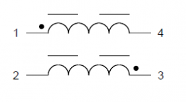
How to connect dual inductor (in single shielded package) in Class D audio Amplifier for SE (stereo) & BTL (Mono) configuration ? Both inductor have opposite starting and finishing winding point (Ex. 7444211415100 from Wurth Elektronik)
Attachments
Last edited:
That's a common mode choke, usually used for power supplies.
You need a single choke for a class d amplifier.
You need a single choke for a class d amplifier.
7444211415100 its specially made for class d amplifier only
Sorry, I missed the "BTL" mode.
1 goes to amp out.
2 goes to amp in.
3 goes to speaker +
4 goes to speaker -
How to connect dual inductor (in single shielded package) in Class D audio Amplifier for SE (stereo) & BTL (Mono) configuration ? Both inductor have opposite starting and finishing winding point (Ex. 7444211415100 from Wurth Elektronik)
Connect "1" to "3" and "2" to "4". Check that you have 10uH before using the choke in the output filter.
NB: Also I missed the BTL aspect. Do as Nigel advises.
That's a common mode choke, usually used for power supplies.
You need a single choke for a class d amplifier.
Probably not. The description hints that it is a common core but the magnetic paths are isolated so coupling between the two inductors is minimised....
In fact,
https://ru.mouser.com/datasheet/2/445/7444211415100-1729647.pdf
It looks like there are two individual chokes mounted on a common base.
I would be inclined to assume that Wurth have chosen the mounting polarity such that PCB routing results in the optimum solution. That would imply that same side pins route to the IC, bridge or stereo mode, the other side pins route to load. Filter capacitors not included.
..
Attachments

Last edited:
Probably not. The description hints that it is a common core but the magnetic paths are isolated so coupling between the two inductors is minimised....
In fact,
https://ru.mouser.com/datasheet/2/445/7444211415100-1729647.pdf
It looks like there are two individual chokes mounted on a common base.
I would be inclined to assume that Wurth have chosen the mounting polarity such that PCB routing results in the optimum solution. That would imply that same side pins route to the IC, bridge or stereo mode, the other side pins route to load. Filter capacitors not included.
..
OK. Can this type of packaging improve any performance or mutual coupling factor because there is also another dual inductor 74441521100 of same product family but this one has same winding position?
Its confusing me as one is for SE configuration or another is for BTL configuration but I don't know which one is for correct configuration.
Attachments
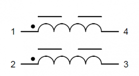
The way it is drawn suggests that it is a dual inductor, with independent magnetic paths, rather than a common mode choke. Analog Devices recommends using common mode chokes for the SSM3302 class D amp, as it allows somewhat lower distortion at high power output. The Wirth dual inductor device could be substituted in the ADI circuit, but you won't get the benefit of the common mode coupling. The symbol for the common mode choke depicts sharing between the magnetic circuits--see L1 and L2 in the schematic below.
Attachments

Its drawn with dots, so the windings are coupled magnetically.
https://www.mouser.co.uk/datasheet/2/445/7444211415100-1729647.pdf
Actually given the paucity of information in the datasheet, who knows what it actually is? Probably two
gapped inductors not screened from each other, so lightly coupled.
https://www.mouser.co.uk/datasheet/2/445/7444211415100-1729647.pdf
Actually given the paucity of information in the datasheet, who knows what it actually is? Probably two
gapped inductors not screened from each other, so lightly coupled.
Last edited:
1. The position of the phase dots
2. The description "inductor" (instead of choke)
3. A value of 10uH/6A
gives me a strong indication of a pair of output inductors for a class-d-amp. These may or may be not tightly coupled.
More likely is the loose coupling.
An appropriate common mode choke should exhibit significant larger inductance.
1. The position of the phase dots
2. The description "inductor" (instead of choke)
3. A value of 10uH/6A
gives me a strong indication of a pair of output inductors for a class-d-amp. These may or may be not tightly coupled.
More likely is the loose coupling.
An appropriate common mode choke should exhibit significant larger inductance.
A common mode choke is marked differently to the one given.
Note continuous lines along sides.
An externally hosted image should be here but it was not working when we last tested it.
Here is the main page: WE-HIDA THT High Current Inductor | Passive Components | Wurth Elektronik Product Catalog. Under "Characteristics" it says: 2-in-1 designs with low magnetic coupling. Also, the page linked above says the dot indicates "start of winding".
These have been around a long time. Here is a link to a dual from Coilcraft that I used about 10 years ago: https://www.coilcraft.com/pdfs/ga3416.pdf
Another dual from Sagami SMD Inductors for Class D DBE1010HB | SAGAMI ELEC CO., LTD.
Here is a quad: Leaded Inductors for Class D DVX1315H | SAGAMI ELEC CO., LTD.
- Home
- Amplifiers
- Class D
- Dual Inductor in Class D Amplifier.