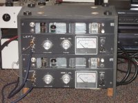
My amps in the Akai M8 chassis are working. I have started a few threads about it, but I wanted to show the finished unit. I completely stripped out the stock circuit. The chassis and stock iron now hold a 12B4 preamp followed by an RH84 (SE partial feedback 12AT7/EL84 design). This amp will soon drive the tops of a biamped open baffle setup. The 12B4 stage will also drive a mini DSP which will be used to crossover to and EQ the woofers (and a subwoofer later!).
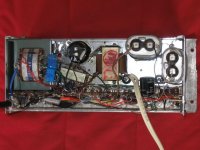
I reused the the stock transformers and choke. I also used the current 30K pot in front of the RH84, and the original speed switch on the back of the pot switches to a little cap that will roll off the fullrangers (that may or may not be the full crossover). I swapped the 1/4" jacks for RCA's. Two inputs, a toggle switch, and pre-out jacks. I drilled out the holes for the original output jacks to install fuse holders. I used to stock sockets, though I did remove one and shift another on the channel that had the 6AR5 (hated the idea of the mono's looking different). I'm using the rectifier filament winding for the 12B4. I added a couple of dropping resistors, as the filament voltage was a little higher than ideal. I put a law faked linear PEC pot in front of each pre (500K pots with 33K resistors). I know it looks a little sloppy. I'm not used to laying things out on that sort of strip, and the additions to the pre section weren't factored in to the original plan.
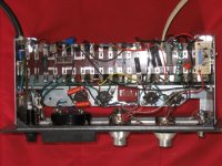
To make it possible with the stock power transformers, I used SS rectification. The B+ on the EL84's is just over 300V (perfect for the RH84). The power transformer stays plenty cool, but I don't have the meter lamp (or meter) connected. I'm using a moderate sized first cap (22uf Nichicon), a giant RIFA second cap (330uf), a 5uf motor run on the 'T7 and a 33uf THSA for the 12B4. Actually, as part of sorting out the pre, I added another RC section, so there is another 22uf in there as well. A la Poinz (and others), I put a couple of 1uf caps across the filament windings. I've also got a couple of 600V film caps across the diodes, and I'm taking the B+ from the CT of transformer.
The RH84 section is built according to the schematic with basic parts. The 12B4 was more of a challenge. It was initially a little unstable (motorboating). An extra RC section didn't help, nor did changing the plate load resistor for a CCS (stacked mosfets). Using a smaller coupling cap eliminated it, but that couldn't be a permanent solution. LED bias finally did the trick. I've currently got 6 ultra bright green LED's per tube. If memory serves (I've been out of town for a few weeks), that's about 15V. The CCS is set at 17ma.
It sounds nice after only a few hours. It is plenty quiet, though the power transformers do make a little mechanical noise (as nearly all seem to on my audio circuit. It drives me nuts). A big improvement over the stock Akai circuit! Compared to my other tube amp (a variant of Eli D's El Cheapo), it fits many of the SE stereotypes. The midrange is lovely. The bass is a bit warm and soft, but my EC has a big iron advantage. This amp won't be used below 150hz anyway. The high treble seems a little polite, but it might open up. Still, what a midrange!
Overall, I'm very happy. I have very little $$ invested in this build, but stripping the original parts out and getting the pre stable did take much longer than I anticipated. Pick up an M8 if you want a fun little project. My wife even likes the look! They are easy to recap, and you may even like them stock. If not, you can do something like this. A phono stage could easily take the place of my 12B4 stage, and it would be easier on the power transformer.
Hopefully I'll soon have the whole system running.
Paul
Wild Burro Audio Labs - DIY Full Range Speakers
I reused the the stock transformers and choke. I also used the current 30K pot in front of the RH84, and the original speed switch on the back of the pot switches to a little cap that will roll off the fullrangers (that may or may not be the full crossover). I swapped the 1/4" jacks for RCA's. Two inputs, a toggle switch, and pre-out jacks. I drilled out the holes for the original output jacks to install fuse holders. I used to stock sockets, though I did remove one and shift another on the channel that had the 6AR5 (hated the idea of the mono's looking different). I'm using the rectifier filament winding for the 12B4. I added a couple of dropping resistors, as the filament voltage was a little higher than ideal. I put a law faked linear PEC pot in front of each pre (500K pots with 33K resistors). I know it looks a little sloppy. I'm not used to laying things out on that sort of strip, and the additions to the pre section weren't factored in to the original plan.
To make it possible with the stock power transformers, I used SS rectification. The B+ on the EL84's is just over 300V (perfect for the RH84). The power transformer stays plenty cool, but I don't have the meter lamp (or meter) connected. I'm using a moderate sized first cap (22uf Nichicon), a giant RIFA second cap (330uf), a 5uf motor run on the 'T7 and a 33uf THSA for the 12B4. Actually, as part of sorting out the pre, I added another RC section, so there is another 22uf in there as well. A la Poinz (and others), I put a couple of 1uf caps across the filament windings. I've also got a couple of 600V film caps across the diodes, and I'm taking the B+ from the CT of transformer.
The RH84 section is built according to the schematic with basic parts. The 12B4 was more of a challenge. It was initially a little unstable (motorboating). An extra RC section didn't help, nor did changing the plate load resistor for a CCS (stacked mosfets). Using a smaller coupling cap eliminated it, but that couldn't be a permanent solution. LED bias finally did the trick. I've currently got 6 ultra bright green LED's per tube. If memory serves (I've been out of town for a few weeks), that's about 15V. The CCS is set at 17ma.
It sounds nice after only a few hours. It is plenty quiet, though the power transformers do make a little mechanical noise (as nearly all seem to on my audio circuit. It drives me nuts). A big improvement over the stock Akai circuit! Compared to my other tube amp (a variant of Eli D's El Cheapo), it fits many of the SE stereotypes. The midrange is lovely. The bass is a bit warm and soft, but my EC has a big iron advantage. This amp won't be used below 150hz anyway. The high treble seems a little polite, but it might open up. Still, what a midrange!
Overall, I'm very happy. I have very little $$ invested in this build, but stripping the original parts out and getting the pre stable did take much longer than I anticipated. Pick up an M8 if you want a fun little project. My wife even likes the look! They are easy to recap, and you may even like them stock. If not, you can do something like this. A phono stage could easily take the place of my 12B4 stage, and it would be easier on the power transformer.
Hopefully I'll soon have the whole system running.
Paul
Wild Burro Audio Labs - DIY Full Range Speakers
Attachments
I think my DMM (cheapo) lies about DC on AC. I've got a DC blocker in the basement somewhere, but I need to put it in a box (live AC on bare alligator clips isn't living room friendly). It didn't help at my old place, but I should pull it out again. The thing is that I get a bit of a buzz on the upstairs stereo circuit, but I swear it wasn't there downstairs on the bench! I'll either sort it out or tolerate it. It isn't as loud as the choke on my EC, nor nearly as bad as the first two power transformers were!
I also owe a big thanks to those that have contributed advice on this project: Eli, Dave, Sy and others. I'm not always the best advice follower, but I would never have gotten this working without you folks.
Dave, once I'm through a bunch of other projects, I hope to revisit this amp and try EF86's as the drivers. I have a stock of 12AT7's and AK was always so adamant that the amp be built precisely as he spec'd it, that I figured I'd try that route first (even though I used an SS rectified supply!). Either that, or as you've suggested Eli, I'll wrap some feedback around the 'T7's, given that I should have enough gain (though it is not as subjectively high as I thought it would be, nor do I have noise problems).
I just needed to get it working so I can get the speaker system sorted out. And then I'll have a sub to build (thinking TH-SPUD clone). And a Twisted Pear DAC to build, CDP mods, measurement gear, an old HP HV supply to restore, etc. And here it is summer time again.
Paul
Wild Burro Audio Labs - DIY Full Range Speakers
The high treble seems a little polite, but it might open up.
Dude,
Look at the RH84 schematic. There's no NFB around the O/P trafo. Ground the "bottom" of the O/P trafo secondary. Connect the "top" of the O/P trafo secondary via a 10 KOhm resistor to the 'T7 cathode. That will return 2.4% of the net O/P voltage, as GNFB. That's little in the way of dB., but it should put some sparkle into the amp's top end.
Eli,
I try that as soon as I can. Soo many projects right now. Even the espresso machine is scheduled to head down to the bench (for a PID controller). And, I do like the RH84 right now as it is!
In the course of searching for solutions to my 12B4 problem, I discovered that many folks have had low frequency instability with them. I urge anyone to try the LED's. I'm not smart enough to know why they were the solution when other attempts failed. But, they're cheaper than one cathode resistor, let alone a bypass cap or a NIWW part! (I was lucky to have a local radio store that sells them in plastic baggies of various quantities). For that matter, the cascaded mosfet CCS was about the same price as a cheap wire wound plate resistor. It does take a little more time to breadboard and adjust though.
Paul
Wild Burro Audio Labs - DIY Full Range Speakers
 New question on M8 split off
 - Home
- Amplifiers
- Tubes / Valves
- Akai M8 rebuild up and running!