Hoping someone can help here...
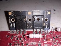
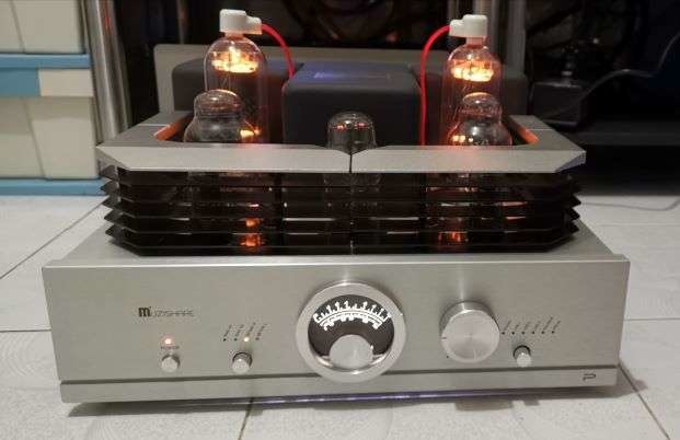
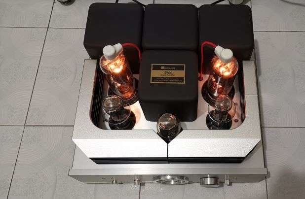
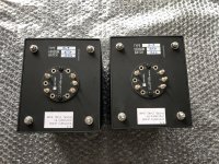
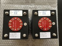
I just purchased a Muzishare R100 Integrated Amp. This version of the amp runs 805 tubes, with a plate (anode?) cap on the top. There is a non-detachable red wire with a ceramic cap on the amp, that connects to the top of each 805 tube.
I got it at a good deal, and it was supposed to be brand new. But, when I plugged it in, I found one of the 805 tubes wasnt working, and no sound coming from that side. I swapped the 805 with the other channel, to confirm that one of the 805 tubes is bad.
Im looking to replace the 805 tubes with something better, but found very few new 805 tubes with the top anode plate cap. There are the PSVANEs that are about $120 a pair, and COSSOR (made by PSVANES) that are $250 a pair.
There are many more options of 805 tubes without the top plate cap. Plus, I think the tubes without the top cap and wire look much cleaner on the amp. I was wondering, can I use 805 tubes without the top cap? And just leave the cap wire disconnected, or have it removed from the amp entirely?
Before you ask, I received no manual with the amp, and cant find any online. Specs are posted at bottom of this thread
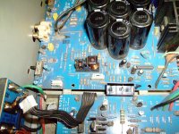
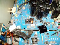
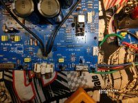
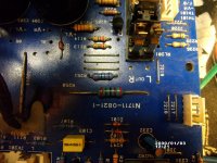
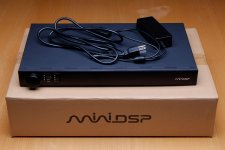
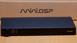
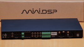
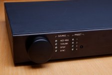
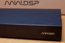
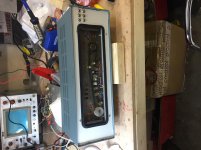
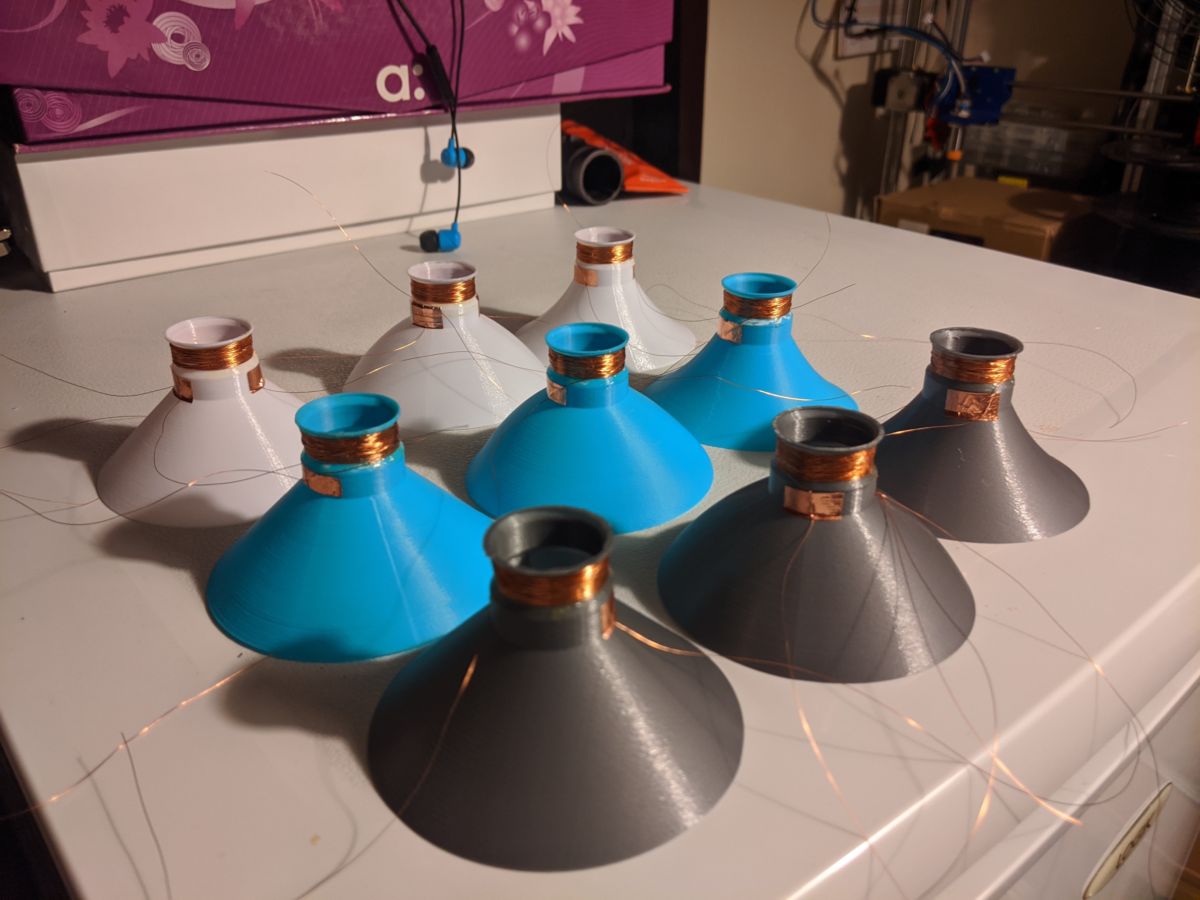
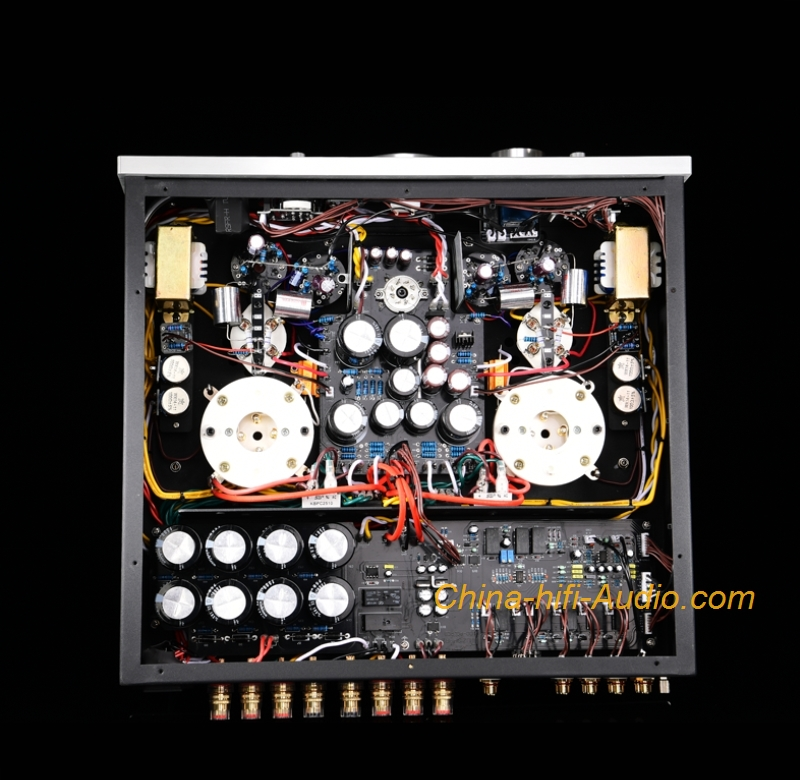
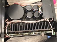
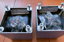
pics of the amp
Features:
1. Handmade, the main circuit is scaffolded.
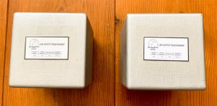
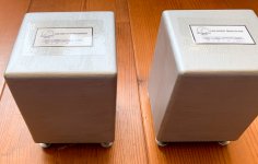
2. Two EI-type single-ended output transformers with high-grade special technology and high-quality broadband response and high quality made by Z11 core.
3. High-voltage power supply and filament power supply independently use two high-power power transformers with Z11 iron core and special materials.
4. The front stage uses two 12AX7 and 6SN7 vacuum tubes; the push part uses two 300B tubes to directly splicing to the latter stage. The tone is full and delicate, the analysis is good, the dynamic is abundant, and the atmosphere is open.
5. The latter stage uses two 805 vacuum tubes for Class A single-ended power amplification.
6, six groups of signal input (PHONO, LINE1, LINE2, LINE3, BAL ANCE, PRE IN); this machine has added a balanced input function and pure post-level function.
7, boot high voltage delay and mute delay function (about 30 seconds).
8, select Japan AL PS high-end potentiometer.
9. Easy-to-install plug-in vacuum tube protection cover.
10. Peripheral power tube bias current adjustment function and power output level meter sensitivity selection file.
11, soft, pure and smooth, suitable for all kinds of music
Technical Parameters:
Rated output power: 50W+ 50W(RMS)
Harmonic distortion: 1% (1kHz)
The whole machine frequency response: 15Hz~35kHz (-1.5dB)
Input sensitivity: 240mV; pure power amp: 1000mV
Input impedance: 100 kohms
Output impedance: 4 kohms, 8 kohms, 16 kohms
Signal to noise ratio: 92dB
Output balance: <1dB
MM input impedance: 51 kohms
MM voltage gain (1KHz): 40dB
MM RIAA bandwidth: 0.25dB (20Hz to 20KHz)
Net weight: 42kg
Gross weight: 48kg
Power consumption: 450W
Use vacuum tube: 12AX7x2, 6SN7x2, 5U4G x 1, 300Bx2, 805x2
Volume (WxDxH): (430x435x265) mm
Power supply voltage: AC 230V (+- 5%) / AC 115V (+- 5%) (50Hz/60Hz)
Working Temperature: 0°C to 40°C, Humidity: 20%~80%
Storage temperature: -20 °C to 70 °C, humidity: 20% to 90%


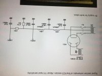


 - remove the current limit, and pray to god it's ok.... Honestly I have had this happen twice by accident with my current limit set at 1A or so, but not with current set higher than this.


