Hello and thank you for accepting me into the forum.
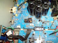
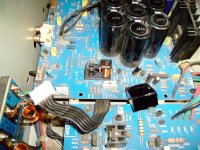
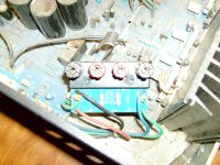
I have a NAD 216 that i purchased used with some other gear it came to me with the speaker PCB broke off of the back and one relay contact melted.
Before i took out the relay to replace it i got the cover off the relay and found the meted contact
Before that i did hook the speaker PCB back up and hooked a pre-amp to it with speakers and it played without going out of protect it had nice sound on the right but the left was scratchy and awful so i decided to replace the relay and check the capacitors in the power supply section i found 6 bad ones and a few suspect all replaced along with the relay (checked all diodes and resistors and transistors also and found none bad in the power supply only)
Now the unit will take some time like 2 min to go out of protect mode or it will do it right away (not always the same time limit) and stay on or it will go into protect and then back on again relay clicking the whole time it will stay out of protect for a while and then it will go back into protect and then back out again sometimes it will stay out of protect mode for quite a while
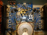
My suspect is either IC201 and or IC202 or both or maybe the left power amp board as i cant not adjust the idling current as there is none i can adjust the right with no problem to the specs of 18mv it seems to me that the power supply is working correctly as the right channel works but im not sure because of the left channel issue i have no ideal how one relay contact can melt without melting the other of the same side see pictures.
I have a NAD 216 that i purchased used with some other gear it came to me with the speaker PCB broke off of the back and one relay contact melted.
Before i took out the relay to replace it i got the cover off the relay and found the meted contact
Before that i did hook the speaker PCB back up and hooked a pre-amp to it with speakers and it played without going out of protect it had nice sound on the right but the left was scratchy and awful so i decided to replace the relay and check the capacitors in the power supply section i found 6 bad ones and a few suspect all replaced along with the relay (checked all diodes and resistors and transistors also and found none bad in the power supply only)
Now the unit will take some time like 2 min to go out of protect mode or it will do it right away (not always the same time limit) and stay on or it will go into protect and then back on again relay clicking the whole time it will stay out of protect for a while and then it will go back into protect and then back out again sometimes it will stay out of protect mode for quite a while
My suspect is either IC201 and or IC202 or both or maybe the left power amp board as i cant not adjust the idling current as there is none i can adjust the right with no problem to the specs of 18mv it seems to me that the power supply is working correctly as the right channel works but im not sure because of the left channel issue i have no ideal how one relay contact can melt without melting the other of the same side see pictures.
Attachments
Last edited:
If the relay is a 'speaker relay' and the contacts are burnt then that suggests a DC offset issue that has allowed full rail voltage to pass to the speaker.
You must measure DC offset before the relay, not after. Check that first.
And the other posters do have a valid point tbh")
You must measure DC offset before the relay, not after. Check that first.
And the other posters do have a valid point tbh
I'm not a professional, but did just finish a complete rebuild on this exact model - had to, the previous owner blew it up completely, guessing by arching the speakers together.
Replace the relays - they aren't cheap, but will need to be replaced if you want to keep it.
I wouldn't worry about the PS as long as you are getting proper voltage on the board (check the 1 watt resistors, I had 2 that were open). Looks like you have ribbon cables with connectors - mine was soldered directly to the board. Either way - disconnect and test all the voltages. As long as you have good voltages move to the amp boards - which more than likely will be where the problem is.
I had to replace all the power and driver transistors on the left channel, but only 1 was actually shorted.
The issue that had me scratching my head was transistors that tested okay, but a bad trace on Q319 and Q321 kept putting it into protection - once I found that and fixed it all would work properly again.
Again - not a professional and although I did a complete re-cap and replaced the whole bank of transistors with matching ones, that probably isn't necessary to get it working.
Thanks to the help of some much smarter guys on this forum, my NAD 216 is working like a charm for the past 6-8 months. I'll be following your progress.
Link to my thread - NAD 216 - Is it worth restoring/saving?
Last edited:
Thanks for all your replies
@ Mooly i have included the schematics along with a hi resolution image of the amp as it is now i believe the relay is a protection/mute relay and not a speaker relay there is only one
@ CaliforniaBob i have been searching in this area also it is kind of overwhelming it would have helped if NAD would have put the voltages on the schematic like they did with the 319
@ Vrystaat Yea the interment relay cycling/intermittent in to protect and then out of protect is confusing what was your solution ? i am assuming you soldered it to both boards ?
One question should i be able to use the chassis/heatsinks as a ground for testing? as i could before replacing a few smaller capacitors but now it doesnt work for a ground i have to use the actual ground
Another observation is that when the unit is unplugged for a while (overnight in this case) when i plugged it in this am and hit the on button the amp went straight on green light after leaving the amp plugged in for a while (and power button in the off position) it will still turn on (green light) but it takes some time like 2-3 min and then after a while will start to cycle again on then off then back on again.
A little history about me i am not a tech per say but i have worked on electronics for most of my life no schooling or what not i own a DMM a transistor/multi tester and a ESR meter
Attachments
Last edited:
@ bullittstang thanks for your reply some voltages are spot on while one is high on the power supply rail (not sure if it will pull down once the left amp board is working properly) unit seems to have a mind of its own atm
I am not sure why i cant use the chassis and or heat sinks for ground for testing as i could before i don't know if replacing some smaller caps corrected a issue with that or made one? i am going to double check my work
You mentioned to ""Either way - disconnect and test all the voltages"" do you mean just the ribbon cables and the speaker input cables ? please clarify
I will try and edit the schematic/and or the amp picture to post voltages on the power supply board
Last edited:
Thanks for all your replies
@ Mooly i have included the schematics along with a hi resolution image of the amp as it is now i believe the relay is a protection/mute relay and not a speaker relay there is only one
The circuit shows that the relay is actually a 'speaker relay' and is used to provide DC offset protection and switch on delay. That would be consistent with the visible burning of the contacts, caused by trying to disconnect a high DC fault current flowing in an inductive load (the speaker).
You have to start at the beginning and measure the DC offset of both channels at a point before the relay.
There is only one relay because it is a double pole type.
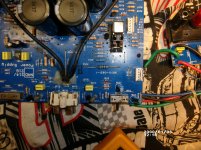
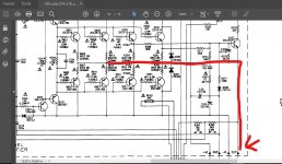
@ Mooly thanks for your information and help i have checked the dc offset before the relay there are pads on the power supply pcb labeled ( L in and R in ) this is were i checked for the offset ( i think this is the correct place ) and it does have somewhere in the 500mv -550mv range on the left channel only i have included a pic of the schematic area and a pic if were on the power supply board i checked if i am correct i would assume i know need to go through the left amp board?
Attachments
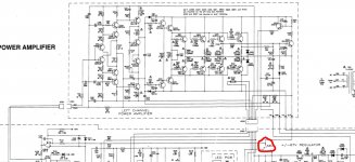
Always work off the circuit diagram... working from pictures isn't easy. The junction of those six 0.22 ohm resistors is the output line and if you look at your first pictures you will see a point marked O/P on the board which should tie up with the terminal marked O/P on the circuit diagram.
That point should be zero volts for both channels. Lets be sure you have the right point first.
If it is wandering around -/+ 500mv then that indicates a problem.
With the amp OFF you could quickly check in circuit that those 0.22 ohms are OK and not open circuit. Can't imagine all (or at least one of each pair) having failed but we need to check.
Attachments
Hello again Mooly and thank you for your assistance
I have checked all the resistors on the left amp board while comparing there values with the right amp board and all read the same for both. none open
I have tested all the electrolytic capacitors ( on the left amp board) in circuit with my esr tester and all read as good
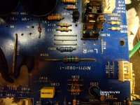
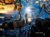
I did find that R317 on the left amp board was open it is a 1/4 (0.25) watt 160k ohm 1% metal film resistor
I have sourced it at mouser 271-160K-RC Xicon | Mouser im not sure about the Temperature Coefficient: 50 PPM / C being correct or how important this is
I am now in the process of testing the transistors on the left amp board for shorts in circuit with my DMM
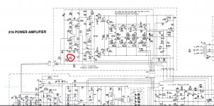
I have included the schematic and marked were the resistor is located. it is fed with the -67 from the regulator circuit
note:
All of the originals caps in the regulator circuit were removed and tested the 2 220uf/100v (C206,C207) and the 4 220uf/160v (C210,C211,C212,C213) were removed previously and tested and found to be good so they were not replaced and returned to the circuit
All the resistors and diodes for the regulator and output protection/mute circuit were checked in circuit and none to found bad
The 4 transistors for the regulator circuit were removed and checked and found to be within specs. hfe
Also the 6 main capacitors (4700UF/80V C202,C203,C204,C205,C901,C902,) (along with all capacitors) were removed and tested with a ESR meter and a capacitor meter for the correct uf and were determined to be good
The 6 that were found to be bad/suspect and replaced with new ones were were 2 47uf/100v (C214,C215) 2 10uf/100v (C218,C219) 2 100uf/100v (C220,C221)
I also replaced 10uf/10v (C229,C230) 10uf/50v from a donor board as i suspected these to maybe bad or bad/suspect/failing in the output protection /mute circuit
I wanted to include the work that i have previously done as i suspected the output protection/mute circuit to be my issue.
But i think maybe the regulator circuit may have caused the fault and went over voltage/spike ect. and took out the resistor R317 because of bad caps in that circuit and or the left speaker connections were shorted in some way (i also suspect this because of the speaker PBC was previously broke away from the amp when i received it and replaced with to long of screws maybe shorting them out? )
Besides the R317 being shorted/open i have -71v on the negative side coming from the regulator circuit and +67 on the positive side would this negative side maybe pull down once the left amp board is in working order? or should i not worry about it for now? as the right amp board works properly
I would also like to note that the mains AC coming off the transformer are not balanced I.E. one leg has a little more voltage than the other maybe like 2 more volts or so could this be the cause of the regulator circuit output to be unbalanced -71v vs the +67 difference?
sorry for all the info not meaning to be confusing i just wanted to post as much helpful information as i could for diagnosis and to maybe help others with similar faults
I have checked all the resistors on the left amp board while comparing there values with the right amp board and all read the same for both. none open
I have tested all the electrolytic capacitors ( on the left amp board) in circuit with my esr tester and all read as good
I did find that R317 on the left amp board was open it is a 1/4 (0.25) watt 160k ohm 1% metal film resistor
I have sourced it at mouser 271-160K-RC Xicon | Mouser im not sure about the Temperature Coefficient: 50 PPM / C being correct or how important this is
I am now in the process of testing the transistors on the left amp board for shorts in circuit with my DMM
I have included the schematic and marked were the resistor is located. it is fed with the -67 from the regulator circuit
note:
All of the originals caps in the regulator circuit were removed and tested the 2 220uf/100v (C206,C207) and the 4 220uf/160v (C210,C211,C212,C213) were removed previously and tested and found to be good so they were not replaced and returned to the circuit
All the resistors and diodes for the regulator and output protection/mute circuit were checked in circuit and none to found bad
The 4 transistors for the regulator circuit were removed and checked and found to be within specs. hfe
Also the 6 main capacitors (4700UF/80V C202,C203,C204,C205,C901,C902,) (along with all capacitors) were removed and tested with a ESR meter and a capacitor meter for the correct uf and were determined to be good
The 6 that were found to be bad/suspect and replaced with new ones were were 2 47uf/100v (C214,C215) 2 10uf/100v (C218,C219) 2 100uf/100v (C220,C221)
I also replaced 10uf/10v (C229,C230) 10uf/50v from a donor board as i suspected these to maybe bad or bad/suspect/failing in the output protection /mute circuit
I wanted to include the work that i have previously done as i suspected the output protection/mute circuit to be my issue.
But i think maybe the regulator circuit may have caused the fault and went over voltage/spike ect. and took out the resistor R317 because of bad caps in that circuit and or the left speaker connections were shorted in some way (i also suspect this because of the speaker PBC was previously broke away from the amp when i received it and replaced with to long of screws maybe shorting them out? )
Besides the R317 being shorted/open i have -71v on the negative side coming from the regulator circuit and +67 on the positive side would this negative side maybe pull down once the left amp board is in working order? or should i not worry about it for now? as the right amp board works properly
I would also like to note that the mains AC coming off the transformer are not balanced I.E. one leg has a little more voltage than the other maybe like 2 more volts or so could this be the cause of the regulator circuit output to be unbalanced -71v vs the +67 difference?
sorry for all the info not meaning to be confusing i just wanted to post as much helpful information as i could for diagnosis and to maybe help others with similar faults
Attachments
Last edited:
Have you tested R317 out of circuit (or at least with one end lifted) ? That would certainly be a very unusual fault... and well done for finding it
The tempco doesn't matter here, just make sure that R317 is a 160k 1% (to match R303).
I wouldn't worry over the regulator voltages as they sound to be within tolerance having looked at the circuit. Its not a precision regulator, the reference voltage is just those two series 33 volt zeners for the negative side and a resistive divider for the positive side. Notice R212 and R213 in parallel. That's an attempt to get the voltages similar using standard parts. The 1 meg across 22k makes a 21.526k resistor.
@ Mooly thanks Yes i have removed R317 and tested it with 2 different DMM and it is definitely open.
Ok on the PPM/C Temoco interesting name i googled that and i am assuming that is referring to the term temperature coefficient. i did a little research on them when i found the R317 interesting
Ok on the regulated supply i understand very good explanation and thank you now to finish checking the transistors to make sure i don't need any replacements with the order of the R317 replacement resistor.
Thank you very much i am learning a lot about electronics it is one of the reasons i wanted to repair this amp myself to learn plus i enjoy it when i am making head way exspecialy.
I own many different pieces of stereo gear 3 complete set up's currently i can listen to receivers and one fisher integrated amp that works and will be next hopefully nothing more that some cleaning of the controls as it works but the phono section may need some work it's a chip amp CA-800.
This is all for myself but i do sell gear from time to time.
Ill comment back after these transistor checks.
Well done you for finding that OC resistor. High value resistors running on high voltages used to be a common failure mode years ago in TV's and so on but a 160k metal film is a high quality part and 70 volts or so isn't really classed as high voltage... in the scheme of things.
If it saw the full 70 volts the dissipation would be a miniscule 30 milliwatts. So very unusual indeed. I would imagine that resistor failing would create a large DC offset at the speaker.
If it saw the full 70 volts the dissipation would be a miniscule 30 milliwatts. So very unusual indeed. I would imagine that resistor failing would create a large DC offset at the speaker.
Hello Mooly i was talking with a fellow mod on our group on facebook about that resistor and he explained to me just what the resistor R317 was for (purpose) i thought i would share it on here so that others may understand and use the info in further trouble shooting with these amps i myself don't quite understand the all his explanation as i am not schooled in the jargon.
He also mentioned that these type of resistors just sometimes fail for whatever reasons and if everything else was working properly i could up the 1/4 watt one for a 1/2 watt for durability i decided not to take that route as i am a purest at heart and do believe that it is a 1/4 watt for a reason and mentioned this in my thinking that it may have saved the left amp board.
His response to that was that one .10 cent resistor vs a hand full of transistors would be better lol
He wrote:
Very interesting circuit. That resistor. Provides negative bias to the emitter of Q303 and negative bias for the base of both pnp transistors. I am guessing there is no sound in that channel since Q303 is an emitter follower for the pnp pair...or distorted sound.
Resistor ordered i am excited to hear this amp in action
Last edited:
That's right. The design of the input stage allows both input transistors (Q301 and Q303) to operate with very small dynamic changes in voltage under all signal conditions and that helps with overall linearity. The current in the upper and lower series resistor chains has to be matched, hence the 1% tolerance for these resistors.
Well i skimped and went with the cheaper shipping it was more than the parts total from mouser UPS/USPS combination type well here it is the 27th of NOV 2018 and the tracking info stopped on the 23rd
I called today and they are going to ship me another order out overnight UPS and it should be here tomorrow with no charge to me as they can not track the package through the USPS for 30 days lessoned learned.
I have had this happen only one other time not with mouser though and i got the package after a refund over 3 months later.
I've been waiting to hear this amp for quite some time and see if i have repaired/troubleshooted it correctly.
- Status
- This old topic is closed. If you want to reopen this topic, contact a moderator using the "Report Post" button.
- Home
- Amplifiers
- Solid State
- NAD 216 Help needed