Hello everyone
I have posted before about my normal builds years ago, and my full range FD51 and FD61 drivers. FD51 is a low power series made for people to attempt and see that 3D printing has potential. FD61 came before and was more capable but more complex and failed as a kickstarter.
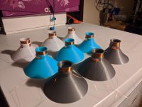
I have started a series where I will be testing different materials with 3 different cone profiles to look at how they react and how viable they would be as materials to use moving forward.
This first video was using common base materials, PLA, PETG and ABS. Just posted in case any of you are interested in this side of the hobby.

YouTube
Paul
I have posted before about my normal builds years ago, and my full range FD51 and FD61 drivers. FD51 is a low power series made for people to attempt and see that 3D printing has potential. FD61 came before and was more capable but more complex and failed as a kickstarter.
I have started a series where I will be testing different materials with 3 different cone profiles to look at how they react and how viable they would be as materials to use moving forward.
This first video was using common base materials, PLA, PETG and ABS. Just posted in case any of you are interested in this side of the hobby.
YouTube
Paul
watched the entire video, very interesting, thank you Paul.
Here are my comments:
Would it be possible to have a paper cone as a reference? Say, a convex shape, if you can only have one... Exact same size as the printed ones, but normal pressed paper
I'm not an expert in 3D printing, but would it be interesting to use the 3D printing for what it excels the most: making complex shapes, that would otherwise be impossible using normal manufacturing process? It would probably require a lot of analysis to find the ultimate sweetspot: rigid, lightweight but damped, and, educated-guess here, I think the 3D printing would allow some kind of bi-structure, progressie structure or sandwich structure where the break-up is better controlled, along with the damping requirements, while having a very rigid and lightweight cone...
I personnally think the key is both the structure and the material; a combination. But the structure is probably the most important to start with, as the 3D printing opens possibilities to think ''outside of the box''
Just throwing a link that might be inspiring...
How 3D Printed Lattice Structures Improve Mechanical Properties - 3D Printing
How 3D Printed Lattice Structures Improve Mechanical Properties - 3D Printing
Structural Advantages
The main reasons to 3D print lattices are the lightweight arrangements and high strength balance it can achieve. It also has major aesthetic benefits with its open spaces, complex nodes and a lot more design possibilities. However, there are also structural benefits that go beyond just strength weight or look.
Another advantage they possess is making use of the most amount of space with a low material usage. Lattices can expand on a design to improve its overall surface area without costing much in terms of materials as they stretch across nodes with a lot of open space in between.
By adjusting the thickness and position of the nodes, beams or struts, designers can integrate some novel features related to how the component interacts with forces and sound. Using lattices gives designers far more control over shock absorption, impact control and vibration/noise dampening. Similarly, designers can reduce impact stress or employ elements that act as a sacrificial features which protect the critical components of the object.
@UserAbuser
Thanks! I am trying to capture some data in a consistant manner so I can use it as a reference when creating designs. More I learn, the better I should get.
@AllenB & Harry72
Thanks for telling me, and I will get a resized version for next time
@ JonBocani
Wow. Thanks for the long detailed reply. Paper maybe. My plan currently is to test a few drivers under the same measuring hardware and then sacrifice one to be fitted onto my magnet motor and suspension so we have a good reference point. I was thinking of sacrificing a PS95-8 from Dayton Audio at this point.
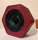
In the FD61 prototypes, the cones were indeed more complex shapes and they do create effects that are desired, but it's always under different conditions. This is the start of bench marking them all in the same way, and this stuff will come in. Here is one of my favourites I made in the FD51 series (Attached)
Oh, and thanks for the linky! Expect not just materials on this platform. I also plan to look at BMR style driver panels on it as well")
@ jamesblonde
I believe so from my long term (3 years) now of experimentation. Cones typically have a thickness of 0.3mm to 0.4mm. Weight is comparable with industry drivers. My biggest issue so far in magnet motor, but this was on purpose for the FD51 series. I wanted a cheap entry point series to show it's plausible, then go for the direct comparison to industry later. This cone platform is 1 of 3 I have planned in my quest to produce this driver. I don't want to just go more powerful. I want to keep improving frequency response and distortion at the same time. I have attached a frequency response of the FD51-4PE driver as this was my best result so far.
Paul
Thanks! I am trying to capture some data in a consistant manner so I can use it as a reference when creating designs. More I learn, the better I should get.
@AllenB & Harry72
Thanks for telling me, and I will get a resized version for next time
@ JonBocani
Wow. Thanks for the long detailed reply. Paper maybe. My plan currently is to test a few drivers under the same measuring hardware and then sacrifice one to be fitted onto my magnet motor and suspension so we have a good reference point. I was thinking of sacrificing a PS95-8 from Dayton Audio at this point.
In the FD61 prototypes, the cones were indeed more complex shapes and they do create effects that are desired, but it's always under different conditions. This is the start of bench marking them all in the same way, and this stuff will come in. Here is one of my favourites I made in the FD51 series (Attached)
Oh, and thanks for the linky! Expect not just materials on this platform. I also plan to look at BMR style driver panels on it as well
@ jamesblonde
I believe so from my long term (3 years) now of experimentation. Cones typically have a thickness of 0.3mm to 0.4mm. Weight is comparable with industry drivers. My biggest issue so far in magnet motor, but this was on purpose for the FD51 series. I wanted a cheap entry point series to show it's plausible, then go for the direct comparison to industry later. This cone platform is 1 of 3 I have planned in my quest to produce this driver. I don't want to just go more powerful. I want to keep improving frequency response and distortion at the same time. I have attached a frequency response of the FD51-4PE driver as this was my best result so far.
Paul
Attachments
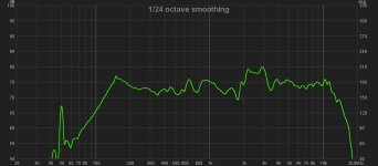
I have attached a frequency response of the FD51-4PE driver as this was my best result so far.
Paul
That's very promising, and I like the shape.
I'm looking at the voicecoils, and wondering if higher efficiency would be achieved with, er, neater windings.
I don't mean to belittle your work - the 3D printed bits look top-notch - but it looks to me like there's an unnecessary compromise there.
Chris
+1
first thing I noticed.
@ JonBocani & AlienB
Thanks. I hope to keep improving as time goes on. Time will tell. The cone shape I came up with due to wanting different lengths between the VC and the cone outer edge, along with wanting the stiffness of the cone to also vary. I like the outcome and expect to use the design again, but this testing will clairfy the best routes for me.
@Chris661
Thanks for commenting and it is not belittling at all. The VC is like this for a few reasons, and yes, one of them in being lazy, but I will go a bit deeper than that.
1) This exact VC gap and cone was derived from my WF81 driver design which uses 0.25mm wire vs these at 0.15mm, so the VC gap was built for a much larger amount of wire. Usually this would be in a much smaller spacing.
2) With my printed designs, I early on hand wound them as cleanly as I could, taking some 15-20 minutes to do one at a time, test and then not like the outcome. This led me to go this route for the reason that (A) I can make and test much quicker (B) It makes it easier for 3D printing users to get involved without needing to be super careful.
This is also why my designs are a under hung magnet motor design and why the motor is weak on these tests. It is easier to adopt more people into this experiment by making it easier and more cost effect to be involved.
As I push upwards in by knowledge and design, you will see the performance increase accordingly. Will there be clean windings at some stage? Possibly, but I would want to design a machine to make them here in house before that.
As to the motor power, this one is only 0.5T, and my next driver planned is to have around 0.7T. With my FD61 prototypes last year I managed to reach 1.1T, so getting to a reasonable power is not a concern. It simply makes the tests and experimentation easier
Paul
- Status
- This old topic is closed. If you want to reopen this topic, contact a moderator using the "Report Post" button.
- Home
- Loudspeakers
- Multi-Way
- Cone Test Platform - 3D Printed Speaker Drivers & Experimentation