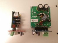
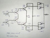
Audiocom Invisus V1.1

I have an Audiocom Invisus V1.1 here which I'd like to use but it is missing most of its capacitors.

I can make an educated guess on what suitable parts might be but I was hoping that maybe someone here might have one of these regs and could tell me what the missing parts are?

P1110461 by Michael Pickwell, on Flickr

P1110460 by Michael Pickwell, on Flickr

P1110459 by Michael Pickwell, on Flickr

Quad 405, R31 overheating

I have a Quad 405 (12368-9) that I am trying to restore and have been following the Dada electronics instructions. Dada (EJP) has kindly helped me via their forum but I still haven’t solved the problem.

I changed all the capacitors, lowered the sensitivity to 1.5v and changed to OPA604 op amps. I changed power wiring as well. Original caps were bulging and crusted. The power caps leaked fluid when I was de-soldering them. The original ul301 opamps were on sockets but the rest of the components looked original. There are no signs of burning on the boards or resistors. The only thing I am not happy with is that I have used 0.25w 3K resistors for R7 and R8. Plan to replace with 1W versions when things get moving here. The chassis is complete apart from the cover which is removed. The clamp circuit was removed and replaced bipolar caps along with new binding posts. I measure -15 and +16.6V going to the op amp. I haven’t done any more voltage checks. I assume the numbers on the schematic are voltages I need to check. I’m a bit nervous of shorting something by mistake as it is a bit cramped.

Both boards worked but had 0.64V DC on the output (both channels). Playing through an old pair of speakers it sounded great. Interestingly, when I unplugged one board I got 0.32v on the output of the remaining channel. I found that by running a wire from the earth lug to the signal earth on the DIN plug I get close to zero DC on the outputs. That is strange as R2 puts 10ohm between signal and power ground. My Proac 1Sc clones have never sounded so good to me. There is a very slight hum on the left channel but that is probably the cable run which needs tidying up. DIN socket wiring is original (shorted earth pins) and I am using the DIN-RCA cable that came with the amp. I made another with 4 core Belden.

Apart from the grounding issue, R31 gets very hot, both boards. Around 72 degC and seems to stabilise there. I have seen this issue on other threads and Dada even suggests putting a higher wattage R31 on the back of the board. I checked all the resistors, pulled a few and refitted and only changed a couple on one board. Still both boards behave the same.
Hope someone has suggestions.
Thanks,
kffern

22k capacitor? and another weird one pictured inside

Hi there,

Pulling some dubious quality caps from a Thomas Organ, solid state made in 1972. some of them are labeled 1000, or less, and I take that to be pf. But then there are several 22k, 68k, 47k, etc marked capacitors (definitely caps, not resistors). Have any of you come across this kind of marking in caps, and if so, what would the value be? I'm guessing .0022, .0068, .0047 uf, respectively. But maybe you know? I don't yet have an LC meter.

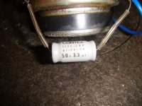
Also, the same brand of caps apear with some different markings. I've attached a picture. I read the markings as standard - it says

p 0.10/10
250~

but I was concerned that it isn't truly .10 uf, as it is a little smaller than another .10 that I pulled off of the organ that was 160v.

Also, is ~ to indicate AC voltage, implying that DC voltage capacity may be actually about 350v?

thanks for any identifying info you may have!

Jeff

Attachments

  • Photo-0044.jpg
    Photo-0044.jpg
    52.1 KB · Views: 494

Elevated DC heater wiring questions

I've never been able to get my 6SN7/6SN7 Aikido with AC heaters completely noise free until I elevated the heater above ground. I soldered in two 100 ohm resistors from CT to each leg and with a voltage divider from a filtered B+ supply I injected about 28 volts DC into the CT. The noise I had enjoyed as I placed my ear next to the speaker was now gone.

A video I had watched on you tube said to have the R2 value less than 100k. I'd never heard of having to stay below 100K before. Mine is roughly 1/2 of that with R1 being 440K. So I'm looking at about 27-28VDC from the divider. So, am I good with respect to what the 6SN7 can tolerate?

I know what I put together isn't precise but I went with the parts I happened to have in my junk box. I am uncertain as to what the elevated voltage should be on the Aikido.

Discrete PWM Class-D Amplifier (Presentation)

Dear all,

I was working the last couple of a weeks on a discrete PWM Class-D amplifier.
Well - basically it's not completely discrete as I still used Op-Amp IC's and integrated Power-Bridges. But still - I did the modelling of the overall control-architecture on my own.

PCB.jpg


It is a single-supply 24V BTL amplifier with differential feedback.


Here a short overview of the measurement results:

Amplifier Gain: 33.5 (26.84 Vpp out @ 800 mVpp in; 4 Ohms load)

Maximum unclipped power: 53.14 Watts @ 4 Ohms (14.58 Vrms)

Differential DC Offset: 52mV (without load), 77mV (with 4 Ohms load)

Total Harmonic Distortion (THD) @ 1 kHz
6.85% @ 1 Watt (4 Ohms load, 2.82 Vrms)
3.16% @ 10 Watts (4 Ohms load, 6.32 Vrms)
2.86% @ 25 Watts (4 Ohms load, 10.01 Vrms)

I shared all the schematics, gerber files, simulation files, measurement results on my github repository:
GitHub - YetAnotherElectronicsChannel/Discrete-PWM-Class-D

If you are interested more in detail, I did a YouTube video about this amp where I explain all the details of the design-flow YouTube

Any feedback for improvements are welcome! 🙂

Thanks,
Markus

Bleeder resistor not needed for "pi" filter?

Hi All,

I came across an article in audio express which states that bleeder resistor is not needed in a "pi" filter in the power supply section. Can anybody shed some light on this, since I am not able to understand what author meant. I always assumed that bleeder resistor is necessary to discharge high voltages in tube rectifier circuits.

The audio express link is: The 2A3 Tube Amplifier - A Tribute to Simplicity and Warm Sound | audioXpress

Thanks and Regards,
Shan

MAGNAT All-Ribbon 2 Crossover - Upgrade Required?

I decided to use the LOCK-DOWN time to peep inside our beloved MAGNAT All-Ribbon 2 speakers - circa 1990, Germany - and check-out the crossover.
(No sound issues - just curious...)

So here's a quick pic.

To these eyes, this appears to be a pretty respectable bunch of components.

Looks like a decent polypropylene cap for the tweeter.
(Please correct me if I'm wrong...)

Air-gap inductor. Nice.

And huge copper ground-planes on the reverse of the crossover.

At 30-years old, one would suspect that the (bipolar) electrolytic caps need to be replaced - assume these are for the woofer - but a bit hard finding suitable alternatives that are not electrolytic.

I know sand-cast resistors have a few detractors, but I have always figured that if DC is not present - as it absolutely should not be - it shouldn't make a difference.

Any thoughts from the panel as to some quick wins here?

I have some nice, low-value MOJO polypropylene caps lying around for bypass duties, if anyone can see the need.

Or should I leave as is?

(No. Sadly, my new ESR tester has not yet arrived...)

Attachments

  • MAGNAT ALL RIBBON 2 Crossover.jpg
    MAGNAT ALL RIBBON 2 Crossover.jpg
    243.4 KB · Views: 293
  • MAGNAT All-Ribbon 2 Home.jpg
    MAGNAT All-Ribbon 2 Home.jpg
    571.1 KB · Views: 298
  • MAGNAT ALL-RIBBON 2 LOGO.jpg
    MAGNAT ALL-RIBBON 2 LOGO.jpg
    799.1 KB · Views: 263

Audio Vois V21 ,V210 pre and power .

I have come across one of these superb pre power combos .
They are +- 24 v split rail pre with Ferranti e line transistors .
Even bias presets on the pre amp boards apart from the buffer .
It has suffered leaky capacitors at one time .
The power amp is quasi complementary largely class b with T03 i
Output devices .
A huge Holden fisher toroidal transformer in the amp .
I’m currently drawing the schematics if anyone is interested .
Gilly

SB Acoustics Satori MTM build

This thread to document a personal speaker build project. So please check back over the next 3-6months. It will be my first set of speakers.

I look forward to all the helpful comments that may be forthcoming.

I have purchased the drivers and xover to build the Martin J King MTM using the SB Acoustics Satori drivers. See his white paper at quarterwave.com.

Per channel these speakers use

2 X MW16P-8
1 X TW29 << I have stumped for the Beryllium version of the tweeter.

Cost = 6 drivers + xover (Hovland 400v caps) in the region of US$1400

References

SB Acoustics
Martin J King white paper
Troels Gravesen SBA-16-MTM

Rationale

I have looked long and hard and various speaker styles and proven projects - full range, 3-way, econowave. I settled on this project for the following reasons

1) I do not have the kit or knowledge to design a speaker from scratch - I need a proven design; one that, obviously, has a BOM that I can source easily from my location

2) I have read and heard good things about these drivers and as I am recently moved to Indonesia I thought it would be a good project to represent the country and a good momento of our time here once we depart

3) I have chosen the MJ King version over the Troels Gravesen version because the xover is fully documented, the values are not proprietary, is available as a kit from the supplier who is providing the drivers. And it was suggested to me that the Gravesen version is better suited to accommodation with suspended wood floors rather than the cement box that I will inhabit over the next couple of years.

Purifi SPK5 crossover options

I'm exploring the merits of internal vs external locations of the crossover for the Purifi SPK5 Demo Speaker design. For convenience I would prefer an internal crossover but, given the compact cabinet dimensions, I'm concerned about the close proximity of the inductors and drivers.
I would appreciate advice on whether it would it be reasonable to mount the crossover on the back of the internal brace (marked in red in the attached image)? Thanks!

Attachments

  • SPK5.jpg
    SPK5.jpg
    210.1 KB · Views: 454

filtering neg leg of a bridge rectifier

I am building a two stage tube amp using a full wave bridge rectifier. Full output would go to v2 and for the reduced voltage for v1, I would like to use the neg. leg of the rectifier.
Here are my questions:
1) Is this possible?
2) Are there special considerations for this type of filtering for either leg to keep the hum down?
3) Since the transformer has a higher output than needed for v2, I am considering using a choke filter system, also for better regulation.
Thanks for your help.

ordered a LM3886 kit, recieved a UPC1342V kit, was I sold a kipper?

After searching these boards for a while I decided an LM3886 chip amp was the one for me, and being in China, I searched for a PCB kit on taobao using that chip, along with a transformer, preamp parts and case to go with it.

The PCB kit arrived today and i realized that the LM3886 chip is mentioned in the title of the product page, but in fact its an UPC1342V chip. The mention of the LM3886 in the title was referring to this one being better...or something along those lines.

After taking a look around, I see very little mention of this chip, so I am a little annoyed (at myself more than anything) as I was keen to get building my LM3886 baby.

So, has anyone got experience using this UPC chip next to the LM or knows how they compare? Sending this kit back is possible, but the weight, and more importantly the time I have to wait are an issue!

Factoring cartridge response into RIAA

Hello

I am curious if anyone has experience with tweaking the RIAA transfer function of a phono preamp to account for the frequency response of a particular dedicated cartridge.

For example, below is the measured frequency response of a Denon DL103R:

An externally hosted image should be here but it was not working when we last tested it.


Could a low-Q bandpass filter be inserted in the network to compensate for the drooping response around 6.5kHz? Or is this just splitting hairs over a few decibels?

Best regards,

Benjamin

  • Locked
Calling all EEs and others

Had a crazy thought. I'm sure you're all aware of the static/running water experiment. I'm envisioning a positively charged screen to repel aerosol/droplets from passing through the grid powered by a battery. Obvious application as a mask against pathogens such as the one we're presently up against. Is this possible? It doesn't need to be any more powerful than stopping anything getting past the grid.

Bought an aluminum amp case - what's the proper way to install parts?

So this is my first time piecing together 2 amp blocks; one block for each speaker. Each block will contain an SMPS and Class D amp.

Today I received my parts - yay, christmas came early! 🙂

My question - what's the proper way to mount individual parts / boards inside the aluminum amp cases?
I mean, I have an SMPS board and an amplifier board, but I can't just glue them to the bottom of the aluminum case 🙂

I could use stick-on plastic stand-offs but I have a feeling that that's not the correct way to go about it..
What's the correct and safe way to install?

Repair help requested - Creek 4240SE

A family member recently gave me a dead Creek 4240SE integrated amplifier. The unswitched outputs were inadvertently grounded together. I found the power supply fuses were blown when I opened up the case. When I replaced them, they quickly blew again (less than 2 seconds). I have contacted Creek to try to get a schematic (the sent me one for my old 4140 a few years ago), but I have not been able to get them to send me one for the 4240, so far.

I am pretty new to the DIY audio world (one Millet Max headphone amp build under my belt), and I don't have much of an electrical engineering background, so I am looking for any help I can get on diagnosing the problem(s) and repairing them. I am an engineer, however, and I have access to most of the tools I could imagine needing (DMM, O-scope, etc). This is not an urgent project, but I am hoping to learn a little about amplifier design in the process. If anyone has the schematic for this amp and can share it, or has any tips on where I should start with debug, I would appreciate the help.

Thanks in advance!

Mullard FM tuner

About five years ago during some web trawling I happened across a Mullard article for a homebuild (!) valve (tube) FM tuner. It was straightforward mono design RF amp/osc-IF-detector stages (no stereo decoder). I would say the year was probably "nineteen sixties" and used the modern valves we are all accustomed to.

I was fascinated, and thought I had saved the file, but it seems to have since disappeared.

It was in the same format as their project articles in the famous "Mullard Tube Circuits for Audio Amplifiers" book, however the tuner project does not appear in either the originals or the reprints of the book.

I guess it could also have been a magazine article but I'm sure it was attributed to Mullard and not just because of the valves used.

Has anyone else seen this, or have a copy or link?

Thanks in advance,
Simon

Crown DC-300A amplifier coil?

For whatever reason R226 (pos lead) popped and the piece flew off damaging L200 (red circle), a piece of its' insulation is missing and at least one wire is open underneath, resistor is no problem, service manual calls for a .5mhy coil

The coil on the other channel measures ~ 7ohms in cct, the damaged one measures ~ 48ohms

I tried searching for .5mh and 500uh axial coils/inductors with ~ 7ohm resistance and not having luck finding a suitable replacement... anything I ever knew about a coil I've certainly forgot sometime in the last 25 years or so... can anyone help finding a replacement?

Attachments

  • DC300A resistor and coil - Copy.jpg
    DC300A resistor and coil - Copy.jpg
    358.9 KB · Views: 455
  • DC300Alistcoils.jpg
    DC300Alistcoils.jpg
    7.4 KB · Views: 457
  • DC300A mainboard - Copy.jpg
    DC300A mainboard - Copy.jpg
    350.9 KB · Views: 538

How to build up confidence during your project?

Recently, I have been designing a project. Actually, it is my first project. The thing is, after my design, i ordered PCBs. But when i get my PCB back, i found I forgot an important feature. So i have to add this feature and reorder new PCBs... Something similar happened several times, which really hit my confidence... And actually it cost much...
It is a bit depressed that i made so many mistakes. Could you pls give me some advice.

TPA3116D2 bluetooth amp board problem

So I bought a chinese amp board with BT to enable my desktop speakers. Connected it and did some listening, seemed fine. Unpaired it and tried another BT source. Not able to connect and seems now undiscoverable, even kills WiFi connections if powered on.... It acts like it can only be paired ones.
The manufacturer seems to be WUZHI and the board partnumber is ZK-502.
Anyone any thoughts?
Appreciate any feedback, tnx

  • Locked
TEAM COVID19-DIY TRISTATE AREA

I am just delving into reading about DIY ventilators. A friend posted on Facebook about the need to 3D print a Y-valve for ventilators.


So first, does anyone near North Jersey have a 3D printer that would like to get involved?

The need face masks and other PPE to start. I’m not entirely sure about the efficacy of DIY ventilators but looks promising

This seems the the Goto place for designs:

Open Source COVID19 Medical Supplies Public Group | Facebook

V-Fets and a Curve tracer...... how to?

Hi I have a Yamaha B2 amp I am goin through. I want to to test the health of these more than the usual Diode and Ohm reading. That is I want to use my
Leader LTC 905 curve tracer , attached file. I have a few of the same V-Fets from a Yamaha Organ amp 2 of the 2SJ26 and one 2SK76. I am feeding the outputs of the Leader to a Tektronix 2445a .

Not very familiar with either, and I was playing around with it yesterday and got some curves but they were very distorted and not useful. I feared I may have damaged the V-fets but doing the simple Diode/Ohm test they read the same as before I used the Leader 905.

SO How do I go about doing this with this equipment?

I tested the 2SJ26 , set the selector to Get, the Base Current/Gate voltage to .5ma and the Collector/Drain sweep voltage to 40 volts .

I had the Horizontal go the the CH 1 (x) on the Tek 2445 and the V go to the CH2 . but that is where I get stuck a bit. I turned the SEC/DIV knob all the way counterclockwise which I think engages the X/Y function.

But not sure what else to do. the signals are very jumpy and flashing.

Any help would be appreciated

Attachments

  • Locked
DIY PPE for aerosol borne contaminant avoidance

Please critique

I'm 63 and need to go food shopping regularly, at a super market. Other people will be there at the same time, so I assume I can get infected with COVID-19 via the airborne aerosol vector.

I was curious if I could make a DIY PPE kit out of stuff I happen to have around the house, so I gave it a shot. The idea is to pump filtered air into a clear, sealed plastic bag placed over my head, gathered at the neck, held in place by a jacket collar.

1st picture shows the system with all the parts connected. I used;

A 12V diaphragm pump, ~12L/min @ 1.5A
A set of 4, 18650 lithium batteries
A HEPA vacuum cleaner bag
A small backpack to hold the system
An adjustable headband, to hold the filtered air stream in place
A clear plastic bag that a blanket or pillow came in.
Silicone hose, a plastic adapter, some glue.

2nd picture shows me wearing the backpack. 3rd, shows me 1/2 hour in, 4th, one hour in. I managed not to asphyxiate myself!

It's hot in there, so I had to change to a lighter jacket at around the 1/2 hour mark. The bicycle helmet is just too hot, so I took apart a headset magnifier for the adjustable strap. (The air stream needs to blast on the plastic just in front of the eyes)

I tested by doing light chores; picking up, some dish washing, walking the dog. It's cool outside and I can feel the new, cooler air in a few seconds when I step outdoors in this getup. Battery voltage remained 12.2V, pump motor case <100 C after an hour of continuous operation, all zipped up in the Camelback.

I figure I can easily get through a 45 minute shopping trip wearing this -

Attachments

  • Components.jpg
    Components.jpg
    496.8 KB · Views: 285
  • Backpack.JPG
    Backpack.JPG
    951.3 KB · Views: 359
  • Half-hour.jpg
    Half-hour.jpg
    787 KB · Views: 305
  • Hour.jpg
    Hour.jpg
    817 KB · Views: 381

Newbie question on DA PC83-4

Purchased 2 of these drivers with the intention to build a set of small ML-TL's. Before the actually build I want to do some simulations to get an idea of what can be achieved. Tried to measure the FS of these and think I measured 107 Hz. Put to one of the drivers about 10 hours of music and measured again: 103 Hz. Way higher compared to the specs: 82 Hz.
I measured using Limp (Arta), the headphone output and a 50 ohm resistor.
As I can't be accused of much experience, thought some on this forum could say something sensible on this phenomenon 🙂

Appreciate any feedback.
-Rolf

  • Locked
Science-based, no politics COVID-19 thread

I'd like to hopefully restart a thread on COVID-19 / SARS-CoV-2 that was going quite well until it was hopelessly derailed by politics. I hope we can keep it civil and avoid discussion of politics, conspiracy theories, and religion as well to avoid burdening the moderators.

Please keep your Illuminati bioweapon or hoax opinion stuff out of here and stick to discussion and posts based in science. If you don't believe in the virus, go post somewhere else.

There are some good (if lengthy) podcasts with virologists and doctors in the US here:

This Week in Virology | A podcast about viruses - the kind that make you sick

Episode 595 and the discussions with Ian Lipkin and Mark Denison are very much worth listening to.

This is also a good video from UCSF, even if the data is 10+ days old now:

YouTube

TSE II - problem with heater regulator

Dear friends,

Please help me to find the problem on my TSE II board (300B tubes)

- T1-GRN1 - T1-GRN2 - measuring 6,3VAC - OK
- jumper from 3-4 - OK
- R2=300R - OK
- R1=100R - OK
- IC3 orientation/soldered - OK
- D1 orientation/soldered - OK
- D5/D4 orientation/soldered - OK
- heater voltage on both 5842 sockets = 7,6VDC - OK
- heater voltage on 300B = 0 ( zerro) !!!
- MIC29502WT - input voltage on PIN2 = 7,6VDC - OK
- MIC29502WT - output voltage on PIN4 = 0 (zerro)
- changing MIC2902WT - still same problem !
- no smoke or anything suspicius, regulator temperature moderate
- HV = OK

I'm really lost here....

BR,
Goran

Update for Lundahl OPT for TU-8200

Hello everyone,
I'd like to know if the are any news about the next realization of TU 8200 OPT upgrade from Lundahl??

Some time ago Mr. Per Lundahl said:

"...With the LL2783 (for Elekit TU-8800) we had a new challenge as the amplifier self-oscillated with our first transformer version. In LL2783B and LL2783C we managed to find a different winding structure which eliminated the oscillations. (LL278C is the final version for TU-8800. It sounds very (very) good. I should have stock in late February)

As far as I understand the modified TU-8200 amplifier has a similar topology and behaviour. I expect that the same winding structure could be used for a TU-8200 replacement/upgrade transformer if this would be of interest. "

Thank you

5670 tube buffer issues

Hello,


I have a cheaply made tube buffer that I removed from a non brand finished product that I wish to modify so I can connect it to a DAC output.
The tube buffer is based on single 5670 tube .


I have 2 issues with it:


1. lower signal output compares to the original signal connected to my amplifier.


2. reduced bass output compare to the original signal, when I connect my source directly to my amplifier there is more midbass and bass but using the tube buffer in the middle the midbass and bass significantly reduced.


I attached a drawing for a reference.


Any help will be appreciated.

Attachments

  • IMG_0384.jpg
    IMG_0384.jpg
    761.8 KB · Views: 223

Crown CE4000 worth the risk?

I have a Crown CE4000 looks like it’s in very good condition no corrosion and very very little dust but it has a couple of blown components, board reference U13 which is a surface mount ic but half the top is blown off where the numbers are, looks like a LM393 which I can see other LM393 chips around there so I assume U13 is the same.
And also board refence U2 which is a VIPer100A located on that offshoot board in the power supply section and that component is blown in half.
All other components look fine.

Would it most likely be just those 2 components? Or does this model have a common fault or something? Is it worth replacing just those 2 components and powering it up? Or is that too risky?

Cheers

Adjusting Gain on PAM8610 amp

Im pretty new to understanding them fully but i have a basic enough understanding so heres the dilemma,

The amp works flawlessly with a direct AC current from the wall, But i want to power it via li-ion battery's, however i always want to limit its current voltage to 8.6vs as the volume etc is fine with this for what it is being used for and here in is where the problems arise!

When i use a boost converter, the moment you go over a certain volume the amp will just keep cutting out and coming back, i know this is all to do with voltage drop and possibly an ampage issue which is fine as i dont need it to go to the volumes its hitting when this happens so onto what i want to do.

I thought about how i would go about using a POT to control the max volume, thats fine if i didn't want to also control the max volume via this POT as this now means i could end up going over the max volume so i thought why not just adjust the gain? and this is where im hitting a wall, ive not the first idea which parts i need to replace on the pam board to adjust the gain so it doesn't go so loud, i thought about adding a couple of POTs onto the board to be able to adjust the gain but im unsure where i would put them...

Thoughts? Advice on this one and how i would go about doing it?

TLDR - i want to adjust the gain but need to know how

Tube power amp for first project - kit or Mullard 3 watt?

Hi there,

I've been itching to build something for a while and recently thought perhaps a cheap(er) tube hi-fi amp would be a nice project.

I have a paid of passive Dynaudio BM6 and also Tannoy Eaton (the original models, 87.5dB sensitivity) with a fairly small living room. I'm going to be playing line level sources and vinyl (through a preamp).

I wondered what people tended to build as a first project? I'm not necessarily looking to build the ULTIMATE valve amp, but I'd wondered whether buying a kit is the best route to go down or whether to build something from scratch. I have built tube gear before (in another life, while I was putting together a recording studio 15 years ago), so I have a handle on the safety aspects, but my actual electronics knowledge isn't amazing in terms of layouts and such.

It'd be great to be able to do something for under £200. I've been looking at something simple like the Mullard 3-watt amp, or maybe one of the EL34 Chinese kits that are on eBay. Perhaps a solid state power supply would make the Mullard design a bit cheaper to build - has anyone experience of doing this, or is there a guide somewhere someone could point me towards?

Very happy to hear your thoughts!

Cheers,

Nat

Help Needed

Can anyone tell me what this is called. I thought threaded bushing or flanged bushing but this misses the fact that it is hollow.

I need to attach this to a plastic container to allow a hose to be connected to drain water away. 1/4” or about 7mm will do the trick

Thanks

Attachments

  • 098B669D-B499-4E78-AB93-AACA12827759.jpeg
    098B669D-B499-4E78-AB93-AACA12827759.jpeg
    513.2 KB · Views: 109

Considering Volumio -need help!

I have some basic Volumio questions. I currently run Puremusic on an old Mac mini (2009, 8g,240gssd, elcapitan)which is due for replacement. I would prefer a silent setup so am considering a volumio or roon based system with the music library stored on a central computer and perhaps anAllo Usbridge to feed my DDDac1794 via USB
My music is currently stored in an iTunes library on an external drive connected by FireWire to the mini. I have 0 experience with Sparky/Linux etc. My biggest question is how difficult is it to get access to the ITunes library if I trial volumio or roon with an Allo usbridge? Is it possible to do a trial and then revert to Puremusic with my library still functional? I mostly listen to my own music collection, about 1000 cds ripped in AIFF format. I do not want to have to rip that many CDs again...ever!
I know these are basic questions. I am a technical person and comfortable doing all kinds of DIY builds but I am not familiar with streamers or their setup. Perhaps I would be better off with a pre built streamer? I am willing to learn and the USbridge seems like an affordable platform to get started.Any advice greatly appreciated
Regards
Brian

  • Poll Poll
Final Sound 150i - finally?

From these speakers, which types do you prefer to listen to?

  • Electrostatic

    Votes: 2 33.3%
  • Planar

    Votes: 3 50.0%
  • Conventional (any number of drivers)

    Votes: 1 16.7%
  • Horn/Loaded/Transmission Line

    Votes: 0 0.0%

I have a pair of Final Sound 150i(s) esl speakers wall mounted as theater speakers next to a TV, small 7 ch system. These are by far the best part.
I have another, larger set of ML esls which we love.
The Finals are, well, nasty little buggers. One of them anyway.
I had followed a suggestion from a diyer years ago - the left speaker was starting to arc - he suggested a careful inspection to locate the arc and a drop of clear nail polish might temporarily fix the issue (fuse/fill the acetate). It temporarily fixed it for 3 years and I owe that guy a round of beers.
The left finally, (pun intended) now seems to be on its last legs. It is arcing badly at turn on (used to be occasional at worst) so all you hear now is a constant pop-pop.
I would love to hear everyone's opinions and hear any other options. Well, good options - I can send them back to the Netherlands to not only be fixed but become new and improved for about $900. Plus $500 shipping, plus insurance. Not practical.
I feel I have 2 options.
1. Repair! Buy the film, $60, buy the spray, another $40, tear that thing apart and fix it! What's the worst that could happen? Problem here is I can find zilch online for help - not one picture, guide, even a thought on physically "how to do this to a Final Sound any model speaker". This is a beautifully machined speaker so a plan would be good. The worst that could happen is a is a deader speaker.
2. Give up! - you love gadgets and esl speakers ARE the coolest in the world, but these are just theater speakers for a TV room! Be a man, spend the $300-400 to get a decent set of mountable speakers. Oh wait, did you just waste $100+ trying to repair the existing speakers? That drops the budget. Of course I want something that sounds awesome for, well, less than stellar prices.
KEF wall speakers? MMGs? These are pretty big bucks.
90% of my current system (more than 20 pieces) was purchased used/bartered so I have so no qualms except for speakers. Buying used speakers has led to some audio and financial pain.
Hope everyone is healthy and safe and your turntables are now dusted off!

Routing: 2.1 System, Hypex Ncore->BK XLS200?

Hello all,

Longtime hobbyist, first-time poster. Big fan of this forum, which has helped me a lot in the past.

With my Coronacation idle time, I've managed a quick build of a Hypex Ncore 252MP-based Class D amplifier kit. It is excellent and, in the two-channel format I'm using it, also a bit of trouble to route to my subwoofer.

I'm wondering: given a two-channel "hifi" amplifier system and limited pre-amplifier routing options, what would be the best way to route from an XLR connection into the XLS200's Speakon input? I want to do this in order to take advantage of the crossover within the subwoofer's amplifier board, and to avoid RF interference across an RCA line from my preamp.

For reference: I am a DJ, using this audio for home practice. Sound is from two ELAC towers (they're...fine). Sources are two Technics turntables into a Vestax PMC-25 mixer. For those of you not familiar with the latter piece of equipment, by far its most superior output signal can be found in the "Main L-R" output, consisting in two XLR male jacks. There are also "Booth OUT" and "AUX OUT" signal options, but these are run with TRS and, in my perhaps-biased opinion, sound inferior.

Hence my need for an XLR-to-Speakon solution. The first option I've tried is to install an XLR y-splitter before the Ncore amplifier left-channel input, routing one XLR fork-end to the amp, and the other to a XLR-to- Speakon-terminated cable for connecting to my XLS200 subwoofer. For reasons I do not quite fully comprehend yet--and would love to understand--the Y-splitter produced: a) very quiet, poor sound to the Left channel, where the connection split was made, and b) absolutely no output from my subwoofer.

What would be a cheap, inexpensive way to maintain Main the signal to my sub?

Thanks for reading, and greetings from Los Angeles,
BN

TPS1035 last hope

Hello!
In a desperate attempt to find this chip I am asking your help. My old but beloved TK2070 equipped amp finally gave up the fight, one of the four output IC-s (TPS1035) is shorted out. I couldn't find any source on the web, so I am asking you guys, maybe someone has ONE piece kicking around in the parts bin. I live in Hungary, and I would pay generously for both the part and the shipping....

About these transformers

Hi there,

I was just testing these transformers I've got from wasted electronics. The big one is giving 11.xx Volts AC and the small one is 9.xx Volts AC but when I'm using a full bridge rectifier made out of 1N4007s and a 1000uF 35V capacitor I'm getting 22.xx Volts DC from the big one and 14.xx Volts DC from the small one.
Small one's DC voltage looks alright but I don't understand why the big one's DC voltage is multiplied this much. Why is it giving higher DC voltage? Is it because the current is higher and the diodes couldn't pass that much current. So in order to balance the power the voltage has raised!!!

Attachments

  • IMG_20200329_142858-001.jpg
    IMG_20200329_142858-001.jpg
    990.1 KB · Views: 233

  • Locked
Coronavirus only holisitic and unorthadox methods please.

Only holistic unconventional orthodox methods allowed in this topic. Any other methods will be erased by a mod if the mods are not biased. SMDH LMAO

Also let me state that this thread is just an alternative to conventional treatments by your physicans/doctors. I am not saying you should not go to the doctor first its just a alternative OVER THE COUNTER supplements that anyone can buy for there health. Since there is no cure or vaccine now while you are infected and in quarantine some of these supplements can help to recover.
  • Like
Reactions: deanznz

Help to improve subwoofer build

Hi, I recently completed my first subwoofer build where I've put together a Dayton Audio DCS165 and a plate amp mivoc AM80 mk2. Tne aim of the project was to create a cheap and small sub to fatten up the sound of the Dali Spektor 2 and marantz PM6005.
When I connected it to the amp I quickly realised that the Dalis are a lot louder, making the sub inaudible.
The sub is connected to the "B" speaker output, both left and right connections.

I would like to save this build by exploring these options
A) check if there is anything wrong with the build
B) Consider a more efficient speaker for the sub
C) Use this sub in a new 2.1 build with two extra speakers matched wit the output of the sub

Attached the WinIsd screenshots, the only potential problem is that excursion at 60W exceeds XMax, so can't really push the driver. I have the feeling in general this is more a driver for a 3 way speaker rather than low-low sub.

I looked into alternatives and the TangBand W8-740P seems a good replacement in a small enclosure, with 1-2db extra output across the whole range (in purple in screenshots attached).

Anyone can shed some light on this project? And can recommend a driver to consider? I can accomodate up to 8" speaker.

Attachments

  • tsm dcs165.PNG
    tsm dcs165.PNG
    29.8 KB · Views: 228
  • cone exc dcs165.PNG
    cone exc dcs165.PNG
    26.4 KB · Views: 227
  • max spl dcs165.PNG
    max spl dcs165.PNG
    29.6 KB · Views: 209
  • max power dcs165.PNG
    max power dcs165.PNG
    26.1 KB · Views: 211
  • project.PNG
    project.PNG
    65.5 KB · Views: 213
  • tfm DCS165 W8740P.PNG
    tfm DCS165 W8740P.PNG
    24.6 KB · Views: 155
  • SPL DCS165 W8740P 60w.PNG
    SPL DCS165 W8740P 60w.PNG
    25.1 KB · Views: 97

Worst PCB track-layout ever?

I am trying to connect components on a Mooly amplifier. I have chosen to make a mono board. I have absolutely now idea on what I am doing and do therefore think that I properly have made every mistake possible. I know I that what I have connected is connected in a random order, but do follow the rats-nest.


I did start by placing every component, acording to the schematic and then moved around as I thought looked somewhat okayish.


Please look at it and give some advice (after your chock!🙂

Attachments

  • Amp1.png
    Amp1.png
    121 KB · Views: 1,061

Cambridge Audio P500 Transformer Repair and Idle Bias

I bought a few projects to entertain myself during COVID-19 'stay home' time.
NAD C356BEE - earlier thread
Next up: Cambridge Audio P500
Symptom:"Won't power up."
Diagnosis was easy - no voltage on power transformer secondaries, primary was open.
My guess was the thermal 'fuse' which was buried inside the toroid transformer.
It's an AUPO 4F 130C device.
AUPO official website, thermal fuses, pptc, manufacturer of bi-metal thermal protector

The transformer didn't look like it got very hot, but who knows? Note to designers- protecting the fuses on the circuit board by burying a fuse inside the power transformer isn't a good idea!
IMHO, of course.... 🙂

Unwinding and rewinding a toroid isn't difficult but it is a way to spend some time..
Check YouTube for videos - the key is to make a bobbin by cutting 'U's out of the ends of a stick.
Wind the tape and wire on bobbins as you work.
I added a 12v secondary for possible use with a speaker protection board.

These Cambridge units have undersized heatsinks. I re-did the thermal paste on the power transistors/micas/heatsink as there never had been much, and it was quite dried up.

Powered up with a dim bulb and everything looked OK, so I plugged the amp into power and checked the idle bias. It was close to spec (13mV between E and S on power transistor) ....a bit below, which is good.

Thanks to everybody who has posted info and schematics on this amp and also the A500 (next up on my bench here); it was a great help. This forum is a fantastic resource.

Checking the bias- notes to other beginners: The hints I found indicated connection to the two leads on the right on the power transistor - these are the S and E leads on the NPN (SAP15 N). For the PNP, it's the two leads on the left that are the S and E connections. Connect to either on each channel for setting the bias with the variable resistor on the board. Those resistors need very little movement to make major changes in bias, so be gentle!
Also, I wouldn't adjust the bias without using 'mini grabber' leads for the voltmeter.

Attachments

  • IMG_0177.JPG
    IMG_0177.JPG
    150.2 KB · Views: 218
  • IMG_0180.JPG
    IMG_0180.JPG
    142.1 KB · Views: 246
  • IMG_0182.JPG
    IMG_0182.JPG
    152.6 KB · Views: 207

RPi Streamer

I made my son a RPi Streamer using the Pi 7" Touchscreen, Allo Piano 2.1 DAC, there is supposed to be a Allo Kali Reclocker but the one I recieved was DOA and due to China parts supply issues they haven't been able to replace it as yet. The Streamer is running Voluimo and all in all it sound good even without the reclocker.
Volumio itself I like, but the App for the phone needs a bit of work, probably only rate the app at 3 - 3.5, were the actual interface would be more like 4.5.

As you will have guessed the Streamer is all acrylic, had a lot of fun making the rear cover and cogged angle adjustment, the bins full of mistakes
default_smile.png
I made myself a clear one originally only because thats what I had at hand and I made improvements to the latest version.

Attachments

  • Front.JPG
    Front.JPG
    272.1 KB · Views: 151
  • Vert.JPG
    Vert.JPG
    326.2 KB · Views: 154
  • Angle.JPG
    Angle.JPG
    353 KB · Views: 149
  • Back.JPG
    Back.JPG
    340.6 KB · Views: 150
  • Bottom.JPG
    Bottom.JPG
    382.5 KB · Views: 116
  • Mech.JPG
    Mech.JPG
    301.4 KB · Views: 101
  • Mech 2.JPG
    Mech 2.JPG
    290.5 KB · Views: 96

Heater-Cathode Voltage in OTL Headphones Amplifier

Hi all!

A while ago I got cheap DAC from China, upgraded it with better capacitors and power supply and got great sound, compared to built-in sound card. The main difference - I got rid of any noises, that caused by videocard or mouse while heavy usage of PC.
Then guys, who gave advises on DAC, recommended me to try build something with tubes, especially cheap soviet (russian) tubes, widely available here in Ukraine. I have lot of experience with microcontrollers, but not with analog electronics, so started searching something easy to get with components I have. That time I found popular DIY OTL headphones amp with simple schematic and only two 6N23P tubes for stereo (first attachment).
After few tests and versions of this amp, I modified its schematic, added vacuum indicator tube, got rid of noise at all and now it looks like perfectly stable.
My final version schematic attached here too.

Just one thing still worry me. After 6N23P I purchased two Tesla E88CC Military grade. They sound much better, but they died after 3 month of use.
I thought issue was with my mains - voltage here vary from 180 to 230 VAC, but I using UPS and it upscales voltage to 205-248 VAC. As result heater voltage without stabilization was 5.9 to 7.1 VAC. (Now I using 16-steps voltage stabilizer, but only for last 2 month).
To solve that I decided to added rectifier and LT1083 for stabilization and got stable 6.3VDC now.
All works nice, but my paranoid brain still keeping one thing - heater to cathode voltage. Schematic is based on SRPP and for bottom stage Ufk equal to 2V, then for top stage Ufk = 114V. For Tesla E88CC tubes this value very close to its maximum (120V), so I got Tungsram E88CC tubes with bigger Ufk = 150V.
I'm very beginner with tube amps and spent tons of time searching for something that could give me idea how to deal with this dilemma, but still have no success.
Some materials, that points me to heater problems and heater-cathode voltage in SRPP:
1. Elevated DC heater supply
2. http://deewm.com/Webcache/The_Valve_Wizard/Heater_Filament_Supplies/Heater_Filament_Supplies.html
3. https://www.diyaudio.com/forums/tubes-valves/346343-cathode-follower-heater-cathode-voltage.html


Maybe you guys can help me? Do I need to elevate heater voltage here? Or disconnect heater ground and leave it floating? But with floating heater I getting noticeable hum with 32Ohm headphones.
Thank you very much!

Attachments

  • original_schematic.jpg
    original_schematic.jpg
    45.8 KB · Views: 176
  • my_updated_schematic.GIF
    my_updated_schematic.GIF
    43.1 KB · Views: 174
  • tesla_e88cc_maximum_ratings.png
    tesla_e88cc_maximum_ratings.png
    79.1 KB · Views: 173
  • tungsram_e88cc_maximum_ratings.png.png
    tungsram_e88cc_maximum_ratings.png.png
    157 KB · Views: 165

The Germanium-only circlotrons. Powerful, wideband.

I report for almost a year's work. Labor is collective.
Series of amplifiers Cyclothers of different configurations. In order to fully utilize the elemental base of germanium semiconductors.
The power band was able to extend from 30-50 to 600 kHz.
Power up to 36 watts. Maybe more.
Amplifiers are very stable.
Stable resting current. Stable output voltage, zero.
Two of the four diodes (VD1-4) are temperature sensors. Placed on radiators
Meander at 100 kHz.

Attachments

  • ??????????_ D3_???_??_.jpg
    ??????????_ D3_???_??_.jpg
    185.1 KB · Views: 1,909
  • ??????????_D3_??????_100_???..jpg
    ??????????_D3_??????_100_???..jpg
    154.1 KB · Views: 1,816

NOS Nichicon Gold Tune 10,000uf 35v caps

I have just over 300 genuine Nichicon Gold Tune 10,000uf 35v snap in type capacitors for sale. these are NOS Wadia stock that i collected years ago and have been sitting around the shop ever since.

Would really like to sell the entire lot, or at least a box at a time. One box is a full 200 and the other has 141


Will consider selling smaller quantities. IE 20 at a time, 50 at a time etc.but will favor a one shot sale.

$150 plus shipping or best offer for the all of them. PM me

Attachments

  • 20200331_112847.jpg
    20200331_112847.jpg
    886.6 KB · Views: 336
  • 20200331_112346.jpg
    20200331_112346.jpg
    730.2 KB · Views: 309
  • 20200331_112902.jpg
    20200331_112902.jpg
    697.6 KB · Views: 323
  • 20200331_112920.jpg
    20200331_112920.jpg
    863 KB · Views: 300

1024-step 10K balanced (4-channel) attenuator

I’ve been keeping this very nice attenuator for awhile but honestly I’ve no time to make use of it. I hope someone who has more experience and time will have a place for it.

A full setup including the attenuator board, control board, power supply board and remote control. I also have the power transformer but it’s quite heavy and would make shipping more expensive.

This is a quad balanced 10K attenuator with 1024 steps. It could be setup to have less steps but I still haven’t got time to look into it.

Price is $190 plus shipping.

Attachments

  • 9F616CF2-F30A-4CCA-8981-60471236D570.jpeg
    9F616CF2-F30A-4CCA-8981-60471236D570.jpeg
    584.7 KB · Views: 404
  • F930F0F4-9A23-4F43-9209-E845F141740B.jpeg
    F930F0F4-9A23-4F43-9209-E845F141740B.jpeg
    587.5 KB · Views: 392
  • EA5BC6E0-1486-46AE-A890-190D8791DCA5.jpeg
    EA5BC6E0-1486-46AE-A890-190D8791DCA5.jpeg
    720 KB · Views: 374

Midrange depression in room response

I recently finished building a new set of active 3 ways and am happy with v1.0 of the crossover, but need some advice on the room response.

The red trace is one 3way speaker from 20" run full range. The light blue trace is from the listening position and is crossed over to a sub at 80Hz. My question is what to make of the depression between 200Hz and 1kHz at the LP. I took measurements along the couch and the width of the depression narrows as you you move along the couch, but never goes away 100%. Filling it in with EQ sounds subtly wrong.

Does everyone EQ the modal region and then forget ignore everything above it?

Attachments

  • 328.1 20in vs LP.png
    328.1 20in vs LP.png
    56.9 KB · Views: 363

Crescendo BC2000D

This is my first time seeing this amp and the audio driver board in the attached photo.

I don't have any faults with the amp i am in search of some threads that use this driver board. The amp is very generic version of type 7 from the tutorial. I am looking for common failures and any other info I can come across.

Attachments

  • 20200331_182140.jpg
    20200331_182140.jpg
    421.8 KB · Views: 116
  • 20200331_181941.jpg
    20200331_181941.jpg
    239.6 KB · Views: 113
  • 20200331_181919.jpg
    20200331_181919.jpg
    974.9 KB · Views: 107

Minidsp SHD not enough outputs.

I bought the minidsp SHD to integrate with some two way Klipsch Jubilees and now I have an unforseen issue. The Jubilee is a two way setup and the SHD fit the bill perfectly allowing me to cross them and PEQ them. As you know the SHD only has two sets of analogue outputs. All should be good but my room has a huge suckout at 65 HZ. I have worked with a GIK acoustics expert moving things inch by inch and not much luck. Bottom line I have to add a Sub and I'm not sure the best way to do this and still be able to use Dirac and not have to another layer of digital to analogue and back to digital. Also I need to be able to EQ the bass bins. I cross the bass bins in the jubes at 500. I'm open to ideas. The sub I plan to integrate is this one the 1802. It mates up well with the Jubes and I should be ok with one.
Cinema Subwoofer - Pro Audio | Klipsch

Denon DP-11F - Platter always spins when unit powered on

I have a Denon DP-11F turntable that I bought in the mid-80's and still use. It works but has developed a couple of 'quirks' presumably due to its age. In a nutshell, the platter spins constantly, any time the unit is powered up. This is a fully automatic turntable, so (if I am recalling correctly!) the platter is supposed to start spinning when the tonearm moves over the record, and stop when the tonearm returns to its cradle. Additionally, the tonearm does not automatically lift and return at the end of the record. The Start/Stop and Lift buttons all work fine. Seems to me like this might be a sensor that is no longer working, but....that's just a hunch, and a general one at that.

Neither of the issues are a show-stopper - I basically just use the turntable like you would a fully manual one. But I would like to return it to its original working order if possible.

Suggestions/thoughts on what the issue(s) might be? I know its not a high end turntable - there is some nostalgia attached to it, but if the cost to fix were too high I would probably opt to put that money into a new turntable.

Thanks in advance. Cheers.

Abusing the output transformer?

Apologies but these are almost certainly stupid questions displaying my complete ignorance.

I have a couple of SE output transformers with 5K and 7K inputs and 4, 8, and 16ohm outputs.

Can I use the 5K tap as an ultra-linear feed to the screen of the output pentode to give a roughly 30%/70% input. I assume this would mean connecting B+ to the 7K tap, the screen to the 5K tap and the anode to the B+ connection.

If I connect 8 ohm speakers to the 16ohm output does this then mean the tube sees a 3K5 impedance?

The OTs are 12VA with a maximum bias current of 60mA

Thanks (ducking )

McIntosh MA-5100 Recap Parts

Hello, this is my first post on diyAudio, but very likely not my last.


Does this look like a solid kit for a McIntosh MA-5100? Overpriced?


McIntosh MA5100 FULL restoration recap repair service rebuild kit capacitor | eBay


Also, I have some experience recapping crossovers and doing some other through-hole soldering. I feel confident doing both, but I'm wondering if this might be over my head. What's the skill level involved for something like this?


Thanks so much, I'm excited to get started in this community/hobby


--JBaeckel

Help 300B se pcb

Hi guys, I need your help!
years ago I made a jelabs 300B se amp, which worked well, but with a bit of hum.
So recently , seen the cost of it, I bought a chinese pcb of a similar schematic, to rebuild mine on a neater layout.
I'm sure you know what pcb I'm talking about, it is shown in the picture attached.
The schematic provided was completely useless, so I ran trough the traces and the real one is attached as well.
Now the problem I am facing is that I have the cathode resistors overheating. If I measure the voltage on the parallel 2k+2k is over 200V!!!
Obviously no sound out of it!


Do you have any idea of what may be wrong with that???


Thank you for any help or suggestion!


Cheers,
Antonio

Attachments

  • frete-gratis-hi-end-300b-pcb-classe-um-kit-amplificador-valvulado-300b-gold-plated-pcb-kits.jpg
    frete-gratis-hi-end-300b-pcb-classe-um-kit-amplificador-valvulado-300b-gold-plated-pcb-kits.jpg
    64.2 KB · Views: 441
  • img20200327_16000277.jpg
    img20200327_16000277.jpg
    203.7 KB · Views: 404

Audio Precision "FFT Scaling" vs Analog Bandpass and Noise

Someone asked why not just use the Audio Precision FFT to analyze noise -- when I tried it initially the results didn't seem correct. Then Jan pointed me to a macro AP had built "FFT Scaling for Noise" -- this corrects level for the different measurement methodologies, ie. equiripple vs none, etc., and corrects the bin size so you're getting results in Volts^2/Hz or Volts/RtHz

When WJ did his seminal regulator articles with a System One in 1995, i.e. the pre-digital version of the analyzer, he mentioned that the bandpass filter in the analog analyzer had a filter factor of SQRT(0.2316). When I got my SYS2722 the folks at AP told me that the bandpass filter used the same factor.

I thus went about writing a macro which took the low level measurements, divided by the gain and square root of frequency and the filter factor to compare input noise.

I am happy to report that the results of both techniques yield results which are entire comparable within a percent or so -- pretty good.

Oh, one more thing -- with the analog analyzer and sweep function -- you can use a "table sweep" and leave out those nasty 50 (or 60) Hz bad apples, just creating a sweep table which cuts out the shoulders of the BP function.

To test, I set up a circuit with an OPA627 for gains of 10X and 100X -- but using resistor Rg and Rf values which varied by a factor of 10 and 100. The noise above the level of the opamp is a function of kT(Rf||Rg)*BW. (When Rg is less than ~100R its effect is almost inconsequential).

The FFT Scaling macro is a battle between precision and accuracy. If you search for a huge number of datapoints you'll have to download the data and RMS the values. With the analog analyzer you can use fewer datapoints and RMS at each frequency to come up with a meaningful answer.

Problems with London City Bulldog / Ashton VP100 tube amp

In short, I have a London City Bulldog tube amplifier. However, this is a "cheap" copy of a Marshall JCM2000 DSL100, which have been marketed in different versions. Another well-known is the Ashton VP100. A slightly different jacket, but identical on the inside to the London City Bulldog.

Now years ago I had the problem that the amplifier pumped loud pops and rumble from speakers when the standby button was turned on.
Turning the level knob all the way to "0" did not change the volume at all. The creaking and popping remained just as loud.
Can't fix the problem at the time. Then put the amplifier in the corner and no longer used. Now I want to get the amp to work again and I have dusted it again. Now the "noises" seem to be as good as gone, but I do hear a constant hum coming from the speakers. This cannot be eliminated by turning the level to "0".
The volume has dropped drastically. Now I have to turn the level knob more than half way to get a little sound. Where normally the whole street would complain if it was on this level.
Then disassembled the amplifier and now I see next, a number of suspicious capacitors. 2 of which have already burst from the jacket.
md84tg06ylx4e.png

The capacitors that have clearly visible burst are the capacitors for the heaters of V1 and V2.
With the other blue capacitors I see no bulging over mess around the capacitors.
To be on the safe side I replaced all the capacitors.
Unfortunately, there is no improvement yet regarding the constant hum coming out of the speaker and the huge dip in the volume.
In any case, I have now excluded that it is in the capacitors. I also measured on the points indicated in the diagram. See image below. instead of +444V I measure +464.6V and where +432V I measure +462.3V. Where I should measure -36V, I measure -39V.

+464.6V compared to +444V seems to me within the margins.
However, I find the difference of +462.3V and +432V. Because the difference in the schematic between those 2 points is 12V. And I only measure a difference of 2.3V.
Is this curious?

What is even more remarkable (or not) is that there is a loop level switch on the back. And when I put a jumper cable in the send and return, I don't notice any difference when I switch this switch on or off.
When I put a pedal between the send and return, it boosts the sound. Is this correct?

I know, there are a lot of questions but I don't know where to look ...
So briefly the problems I have:
1. Volume dropped drastically
2. Constant hum on the speaker. (does not respond to knobs)

Does anyone have experience with this amplifier or related or can someone help me with troubleshooting, I would like to hear it.
Thanks in advance.
l2zwkl5a6y.png

REL Strata 1 - high level input failure

Hi everyone and a Happy New Soldering Year!

Just wondered if anyone could point me in the right direction here with this fault?
I can solder, I have a few bits of test equipment eg multimeter / capacitance & inductance meter + a variety of soldering irons & proper leaded solder BUT I am not electronically trained so basic level knowledge (i.e: I understand some of what a capacitor/inductor does re frequency attenuation and appreciate the hazards of a charged cap/mains voltages etc).

On that basis would anyone know what I might look for on the plate amp to replace to get it back working?

The low level works but I don’t like using it in my music set up I have.

Many thanks in advance & appreciation of any help offered here. 🙂

10F/RS225 FAST / WAW Speaker XO PCB GB

Edit Feb 9, 2020: XO PCB all built up with components from BOM
809239d1579155037-10f-rs225-fast-speaker-xo-pcb-gb-10f-fast-xo-pcb-built-03-jpg


Works well as 2nd order passive XO for MTM speaker too:
815059d1581099133-10f-rs225-fast-speaker-xo-pcb-gb-mtm-xo-build-jpg


This is the Group Buy thread for the PCB for the XO for the speaker described here:
10F/8424 & RS225-8 FAST / WAW Ref Monitor

After making the XO using P2P for years, and at the request of members wanting to try this speaker, I have asked JPS64 to design a layout for this 1st order transient perfect crossover.

Here is the schematic from Xsim:
802764d1576593944-10f-rs225-fast-speaker-xo-pcb-gb-ab5faeb4-e6fd-4c24-a2ff-d3165da6ba74-jpeg


Here is the predicted response and phase using measured response:
802765d1576593944-10f-rs225-fast-speaker-xo-pcb-gb-66f2b891-d8bb-4172-9c01-531c8f40636b-jpeg


Here is the measured response - note the flat phase from 100Hz through 10kHz - essential for reproducing the transient dynamics correctly:
802766d1576593944-10f-rs225-fast-speaker-xo-pcb-gb-7309759b-62d2-437c-bcba-d69529fe47d4-png


Here is the measured step response (right triangle is idea transient perfect response):
802767d1576593944-10f-rs225-fast-speaker-xo-pcb-gb-ebedf9ad-094c-44ff-b4ac-931bd13d405c-png


Here is what the P2P XO used to look like:
802768d1576593944-10f-rs225-fast-speaker-xo-pcb-gb-3dbd58e4-5b93-4ebe-a245-be941d6476ac-jpeg


Here is the PCB schematic:
802769d1576593944-10f-rs225-fast-speaker-xo-pcb-gb-34934b34-511a-47c6-af69-944d8b33940e-jpeg


Here is the layout (board is 150mm x 110mm, 4mm dia holes are 140mm x 100mm). Connectors will be Faston spades with optional flying lead solder pads for 16ga wire. Holes will be provided to zip tie the inductor and heavy large capacitors to the board:
802770d1576593944-10f-rs225-fast-speaker-xo-pcb-gb-d2385983-f9bd-48cd-b213-656503d855d3-jpeg


Thank you to JPS64 for another outstanding design!

Here is the list of components (all from Parts Express) for a stereo pair:
Code:
Product       Name	Sku	 Qty	 Price	Total
Dayton Audio DNR-4.7 4.7 Ohm 10W Precision Audio Res	004-4.7	4	$1.09	$4.36
Dayton Audio DMPC-27 27uF 250V Polypropylene Capacitor	027-439	4	$8.58	$34.32
Dayton Audio DNR-0.51 0.51 Ohm 10W Precision Audio Res 004-.51	2	$1.38	$2.76
Dayton Audio DNR-10 10 Ohm 10W Precision Audio Res	004-10	2	$1.38	$2.76
Dayton Audio DMPC-2.2 2.2uF 250V Polypropylene Capacitor	027-415	6	$1.87	$11.22
Dayton Audio DMPC-6.8 6.8uF 250V Polypropylene Capacitor	027-424	2	$2.75	$5.50
Jantzen Audio 4.0mH 18 AWG Air Core Inductor Crossover Coil	255-280	2	$20.91	$41.82

Boards will be thick 2mm thick FRP, 2oz copper with thousands of via stitched holes to tie identical planes on both sides for low impedance), ENIG finish, green solder mask. Pricing will be $38 ea. Shipping will be the usual tracked first class parcel, auto-calculated in Etsy (about $6 in US, $14 CAN, $23 everywhere else).

If you are interested please add your name, quantity of boards, country below:

Name Quantity Boards Country
xrk971 4 USA

Attachments

  • AB5FAEB4-E6FD-4C24-A2FF-D3165DA6BA74.jpeg
    AB5FAEB4-E6FD-4C24-A2FF-D3165DA6BA74.jpeg
    45 KB · Views: 1,970
  • 66F2B891-D8BB-4172-9C01-531C8F40636B.jpeg
    66F2B891-D8BB-4172-9C01-531C8F40636B.jpeg
    95.4 KB · Views: 1,658
  • 7309759B-62D2-437C-BCBA-D69529FE47D4.png
    7309759B-62D2-437C-BCBA-D69529FE47D4.png
    80.1 KB · Views: 1,599
  • EBEDF9AD-094C-44FF-B4AC-931BD13D405C.png
    EBEDF9AD-094C-44FF-B4AC-931BD13D405C.png
    55.5 KB · Views: 1,543
  • 3DBD58E4-5B93-4EBE-A245-BE941D6476AC.jpeg
    3DBD58E4-5B93-4EBE-A245-BE941D6476AC.jpeg
    422.7 KB · Views: 1,615
  • 34934B34-511A-47C6-AF69-944D8B33940E.jpeg
    34934B34-511A-47C6-AF69-944D8B33940E.jpeg
    107.9 KB · Views: 1,640
  • D2385983-F9BD-48CD-B213-656503D855D3.jpeg
    D2385983-F9BD-48CD-B213-656503D855D3.jpeg
    171.8 KB · Views: 1,996
Projects by fanatics, for fanatics
Get answers and advice for everyone wanting to learn the art of audio.
Join the Community
507,650
Members
7,882,730
Messages

Filter

Forum Statistics

Threads
405,964
Messages
7,882,730
Members
507,650
Latest member
Sanjiev