Lexicon omega problem
- By mreeveshp
- Digital Line Level
- 20 Replies
I have had my omega for quite a few years now and I used to record a lot but now I mainly use it to listen to music or play music through my studio speakers to play guitar along with.
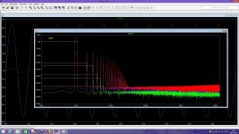
After a while I started getting a bad hum through my speakers and yesterday when I tried to record the hum was in the recording.
Also when I turn the monitor mix and mainly the output level I get horrible cracking through my speakers and then one or the other speaker will quit playing until I find a sweet spot that gets both speakers playing.
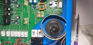
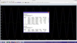
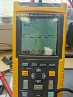
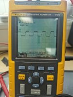
I thought about taking the case off and at least spraying everything down with canned air and maybe get dust out and see if that will work. I'm just worried that if I mess it up I won't be able to use it to listen to music. I have a picture that shows that even with everything unplugged the levels are up 2 bars.
Does anyone have any ideas that might help?
Sent from my SM-N950U using Tapatalk

After a while I started getting a bad hum through my speakers and yesterday when I tried to record the hum was in the recording.
Also when I turn the monitor mix and mainly the output level I get horrible cracking through my speakers and then one or the other speaker will quit playing until I find a sweet spot that gets both speakers playing.
I thought about taking the case off and at least spraying everything down with canned air and maybe get dust out and see if that will work. I'm just worried that if I mess it up I won't be able to use it to listen to music. I have a picture that shows that even with everything unplugged the levels are up 2 bars.
Does anyone have any ideas that might help?
Sent from my SM-N950U using Tapatalk
![IMG_3259[1].jpg](/community/data/attachments/771/771140-57a1562d387e688def0da9944073c496.jpg?hash=V6FWLTh-aI)
![IMG_3260[1].JPG](/community/data/attachments/771/771160-5ebe85022ad1bd8db26e82e131e5fc5c.jpg?hash=Xr6FAirRvY)
![IMG_3258[1].jpg](/community/data/attachments/771/771187-3537a326d7b2463e2290057fa356e63b.jpg?hash=NTejJteyRj)