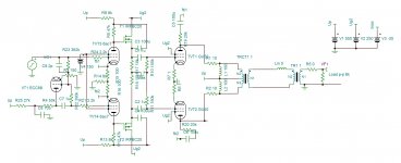
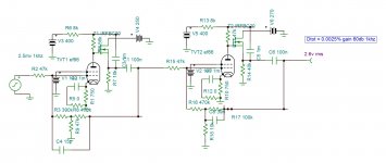
By giving a hand to zintolo with his GU50 projects I came upon this circuit. The bootstrapped pentodes provide a gain of 75db ,yielding 40 ohms plate to plate output impedance for 6k load by plate to cathode feedback. The input inverter comes from Audio Research D70 , It can function without by parafeed mode but oscillates on saturation. Using Ayumi models the amp exhibits 80w with 0.03% Dtot.
Attachments
One of the Western Electric amps has those same local feedback paths.
The addition of the fets in this design seems rather unique.
The addition of the fets in this design seems rather unique.
DC coupling from FET to grid (and separate FETs gate from previous stage -alá Powerdrive- ) is better option.
Last edited:
GU50 in zero bias?
There is a hard to read Vbias label at the junction of R10 and R11. I agree that capacitive coupling is an invitation for blocking distortion, but I have no experience with the GU50, so I don't know how close to zero grid voltage you need to get on big positive going transients.
The addition of the fets in this design seems rather unique.
They are the "bootstraps" that raise the apparent load impedance on the driver tube to get large gain and lower distortion. The high gain is needed to overcome the feedback from the output tube plates to the driver cathodes.
I use a similar bootstrap technique on the pentode input stage in a little guitar amp to get voltage gains of over 1000 (60 db) from a single stage. The limiting factor is microphonics. Too much gain in a tube makes for a good microphone.
I doubt there are any "new" topologies out there. This very much resembles the design from the RCA Receiving Tube Manual (RC-30; p. 696) The second gain stage uses output buffered 6AC7s with bootstrapping to elevate the effective Rac of the 47K plate resistors, again, not exactly new, and it's been used in the place of designs like the Mu Stage for gain, or with very small feedback capacitors to speed up circuits that need to process fast pulses. Bootstrapping was also very common in SS design practice to replace CCS active loads.
TR1 1 from that schemo looks to be a plate modulation XFMR, and a 6K load for VF-1 is definitely in the ball park for the audio impedance of a Class C final.
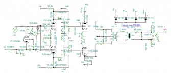
edcore cxpp100-6.6k

I adapted the amp for 90$ cost Edcore cxpp100-6.6k output transformer. Considering high insertion loss and higher impedance , the plate voltage passed from 550v to 650v bias from 46ma to 34 ma , screen 250to 270. I don't know if the bias current is sufficient to overcome glitches due to primary-primary mutual inductance. To get better phase shift at 20khz I decreased the internal feedback by five fold to apply it from the output of 14db, frequency responce 100khz. The distortion is 0.04% at 1W 0.06% at 80w and reaches at clipping 93w 0.1%.
I adapted the amp for 90$ cost Edcore cxpp100-6.6k output transformer. Considering high insertion loss and higher impedance , the plate voltage passed from 550v to 650v bias from 46ma to 34 ma , screen 250to 270. I don't know if the bias current is sufficient to overcome glitches due to primary-primary mutual inductance. To get better phase shift at 20khz I decreased the internal feedback by five fold to apply it from the output of 14db, frequency responce 100khz. The distortion is 0.04% at 1W 0.06% at 80w and reaches at clipping 93w 0.1%.
Attachments
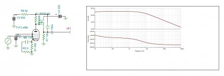
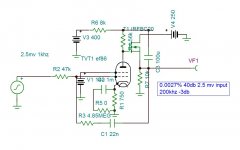
It is possible to get a gain of 5000 with 6ac7 and 3000 with EF86. To make a phono preamp of 40db (RIAA not implemented) with EF 86 0.002% max Dtot is possible. Adding a same resistor on the drain , It can deliver phase split with very high gain to replace advantageously input stages of amplifiers as ST70.


Attachments

Thanks kokoriantz, nice variation for the circuit I would like to finish (at least on paper).
I'm following the thread.
Just one question: you say 200 kHz for -3dB, but from the plots you showed here seems way lower than that (the ordinates show already values in dB).
Thanks.
I'm following the thread.
Just one question: you say 200 kHz for -3dB, but from the plots you showed here seems way lower than that (the ordinates show already values in dB).
Thanks.
If you look closely you can see the feedback loop going back to the grid. So thus it explains the 200Khz bw.
I think that especially resistor R2 may contribute to some sub-par noise behaviour of this circuit.
Best regards!
Best regards!
You are right . In voltage mode the inductance shorts the infra frequencies of the noise generated by R2, in current mode it reveals it. I have seen such current mode input preamp used in projection chambers in movie theaters where the turn table should be several meters away from the preamp capturing lot of noise from the projector. May be capacitor in series resolves the problem.
Hi kokoriantz,
I've found this circuit (page 14 of this pdf: http://www.tubebooks.org/file_downloads/RCA_HiFi.pdf ). It seems to implement your solution together with others and give very good results without UL taps.
EDIT:
Wavebourn talked about this schematic here: Shunt feedback options
I've found this circuit (page 14 of this pdf: http://www.tubebooks.org/file_downloads/RCA_HiFi.pdf ). It seems to implement your solution together with others and give very good results without UL taps.
EDIT:
Wavebourn talked about this schematic here: Shunt feedback options
Last edited:
- Home
- Amplifiers
- Tubes / Valves
- Is this a new topology?