NAD 304 bias problem

Hello,
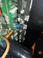
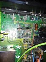
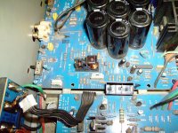
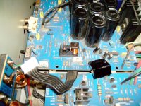
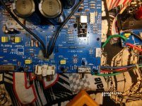
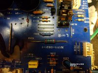
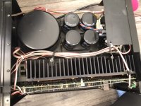
after finishing a long recap and resistor upgrade on my NAD 304, I was following the alignement procedure for offset and idling current.
I did it one time and after listening some music for 10 minuts, I disconnected the speakers for a 2nd and final adjustment. While I was doing it the wire connected to the TP301 touched the metal case ( ground) of the amp, before I had the time to move it I saw some sparks.

Now the trimpot turns without any change in the idling current, it always shows something around 0.01 mV, on both channels same stuff.

I thought the amp was ready for the bin , but actually I connected to a pair of "suicide speaker" and it works.

I'm still worried about the idling current, do you have any idea of what happened? What component could be faulty ?
I tested the 10k pots with a multimeter and they seems ok.

Any help is welcome

Max

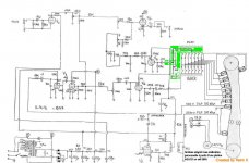
Here a detail of the schematic withh the TP301 and the bias trim highlighted detail schema nad 304.pdf - Google Drive


here the service manual with the full schematic nad_304_sm_2.pdf - Google Drive

riser card for soundcard

Hi And thanks for reading.


I am plagued with weird noises from my asus stx2 soundcard, crackles, whistling noises.


What do you think of a pc ribbon riser card to physically move the soundcard away from the pc and all the interference.


https://www.ebay.co.uk/i/1241351624...MI_s3xxePa6AIVGeDtCh3OoQWhEAQYAyABEgJkPvD_BwE


Do you think there may be an improvement in sound quality, or is the noise i am experiencing mixed in with the audio signals so is too late to do anything about


Thanks.

Alpine 1507 power supply issue

Not really sure if i need to post this here. But i picked up an old Alpine 1507
and when i bought it it powered up fine. I took it home to clean it up a bit and when I went to hook it back up the power light comes on with a solid red. None of the other lights come on. Iv checked the resistance of all the "fets" and iv visually inspected both the top and underside of the power supply and amp boards. No visual damage is present. The fan no longer spins either. So iv tracked the issue to being on the power supply board.
But i have no idea where else to look for issues. Id really like to my money not to goto complete waste on this amp. Im convinced whatever is wrong with it can be fixed.
Any help is greatly appreciated

HT power supply and output capacity (LM317HV) for Phono Preamplifier

Hi! I have an HT power supply made by me in operation..on a 1000-hole base ... in my prehono with light bulbs (valves). 🙂
The scheme is not my work..but it works quite well.
I still have a little noise towards the low end of the spectrum..with a small peak at 100Hz ... a little at 200Hz ... and some varied noise below 100Hz ... 50Hz zone.

But taking a look online ... on similar schemes ... I notice that there are different capacities than mine.

I refer specifically to:

- In mine I have a mkp capacity of only 0.1uF at the output of the Mj13009 (I also see 22uF mkp on the net ... of which I attach the diagram) ... which is then also being at the input of the LM317.
On the net I see schemes with very different capacities. The LM317 datasheet speaks for the input ... up to 1uF.

- In mine I have a capacity of only 3.3uF electrolytic .. output from the LM317. The datasheet speaks up to 25uF ... I also see 33uF on the net.
Maybe with higher capacities there is to add a protection diode (booooooo.. I don'tknow).

- In mine I have a capacity between the pin adj and the ground from 0.47uF when on the datasheet of the LM ... it says up to 10uF ... for the best results.

It seems that my scheme..and therefore power supply is with the values ​​reduced to a minimum. They made economy!

Since I am making a friend (a little too expensive $$$) unravel the scheme because I would like to make it decently on pcb..and definitively ...

I would be asking you if perhaps it would be better not to optimize these skills in such a way that made the pcb.
I don't think about it anymore.
But, in fact, I have to decide (best capacity) before doing the pcb ... breast 'I'm screwed!

The data ... compared to the capacities ... that I read on the datasheet of the LM but I am not able to understand them well .. I don't know how important it is that in any case my work at 250 and passes volts.
I would not, loading too much Mj13009 and Lm ...., fry them .. or make them work uncomfortable.

I have several electronic materials available and I could draw from them what I need.
Specifically, I also have beautiful vishay mkp caps from 22uF 400vdc ... which could be perfect for Mj13009 and Lm output ... but I ask you.
I also seem to have 10uF mkp 400vdc..I have a vague memory.


The preamp absorbs about 7 / 10mA maximum..I think.
From the Mj13009 I go out with about 275/7 vdc and I go to power the output stage V3 which is an ecc81 but in the future I could opt for ecc82.

From the LM317hv..out with 255/8 vdc and go to power stage V1 and V2 (both ecc83).

From the leveling I arrive to the stabilization with about 300vdc.

For the filaments, which I run at 12.6vdc ... as I have found better results in terms of noise compared to 6.3vdc, I have 2 pcb power supplies based on LT1083.
One for the filaments of V1 and V2 ... the other for the filaments of V3 (of which the relative divider is missing on the diagram ... but on the final pcb there will be ....)


Capacitors added in blue on the diagram, "around" the zener ... currently I have not mounted them but I am going to add them to the final pcb.
I copied these caps from internet schemes ... where they are defined as "equalization" ... perhaps more than equalization which maybe was a term error ... they are used to filter-clean any noises .. rf .. etc...

Thanks if you help me understand if I can do better than the diagram below. I am referring to the capacities intended as type and value.


Here is my scheme .. ugly..made by hand..but you understand:
PS: the R value of the divider for the filaments are incorrect. Those written were for when the filaments worked at 6.3vdc.

Datasheet 317hv: https://www.ti.com/lit/ds/symlink/lm317hv.pdf?ts=1588375219843


.. this below instead is a scheme taken from the internet that I know is an excellent scheme! If I'm not mistaken, it was a scheme made for a pre-amplifier like mine.
I report it only because I see that it has 22uf mkp output for the HT..and for coincidence .. those big and expensive capacitors I would have them already in my drawer...but I don't know if to use them.
They are just a little bulky .. but I would gladly use them if they are needed ... if they can filter better.


I'm sorry if I wrote too much. I also apologize for my bad English.

Yamaha HS80m get's louder sometimes

Hi everyone,

one of my HS80m's sometimes starts to rustle and then the speaker suddenly becomes much louder on its own than the other speaker.
The problem only occurs from time to time.
Last time wehn I had this problem it went away after 1 hour of trying to find out what's wrong then i just turned up volume on my mixer and it was gone.
Maybe someone has the same problem and could give me some advice.
I thought it could be the mixer so plug them into my soundcard but the issue was still there.


I have checked all the cables, mixer and the audio interface and they work just fine without any problems.

Cheers

AVi labs amplifier 1v DC offset

Hi,

I need some serious help. A friends Avi labs amplifier has gone dead in one channel with 1v output. He's not sure if output shorted or not but sounds like it may have.

There are no fuses, or burnt components! but the right channel does not have any sound and has 1v output.

I have the amplifier with me so I have lots of pictures.

I'm not new to this forum but far from a pro in terms of trouble shooting.

I tested with a MM and the amplifier off all the output transistors and they all measure fine?

Attachments

  • IMG_20190728_214723742.jpg
    IMG_20190728_214723742.jpg
    247.6 KB · Views: 319
  • IMG_20190728_222221142.jpg
    IMG_20190728_222221142.jpg
    436.2 KB · Views: 321

Transfer Function Magnitude WinIsd

Transfer Function Magnitude WinIsd Reference Window?

Hello, I am modeling a Ciare HSG 200-44 in Winisd and have a question about transfer function magnitude. I am going for the flattest response here with a tuning of 34 HZ. I am using the Extended bass shelf -3db alignment option since that option suggest a similar size enclosure to what I have, which is 1 cf.
The Quasi Butterworth is supposed to be a flatter response but it suggests an enclosure that is way to small....tuning to 34hz there would be no room for the port in that small of an enclosure. I would really like to be in the 20's but I do not think that is possible, mainly due to the hi increase of port noise. I am using a 3 1/2" dual flared port at about 20" long which is about all I can fit in my 1 cf enclosure.

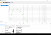
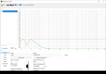
I have played around with the driver and came up with a pretty good looking response, however the Transfer function magnitude graph looks a bit funny.
It is flat in the required frequencies but it is not in the desired reference window of 0 to -3 db. Does it really matter if I am "in the window" on the TFM graph...the SPL graph seems good! So I am confused when comparing SPL to TMF.

I am posting some pictures of the charts to show what I have, as well as the driver specs. I have entered 250 watts for the signal.

I am not dead set on this driver but it has a higher spl that other options.
It has to be an 8" 8ohm driver. I have an available 300 watts(rms) for my sub. My setup is a 3way powered speaker and I have a nice dsp setup so
I have many xover options. Butterworth, Bessel, and LR, up to 3rd order.
(Note...I have added a lp and hp filter in the model)

The only other driver I could find that will fit the bill is a Dayton RSS210HO-8

The Dayton looks better on Winisd but the SPL is a good bit lower which is leaning me towards the Ciare.

Anyway I would greatly appreciate any help and or advice, especially with the transfer function magnitude(since that is what this post was really about)!😎

Attachments

  • 2020-05-03 (1).png
    2020-05-03 (1).png
    101.8 KB · Views: 164
  • 2020-05-03 (2).png
    2020-05-03 (2).png
    101.8 KB · Views: 164
  • 2020-05-03 (3).png
    2020-05-03 (3).png
    948.1 KB · Views: 142
  • 2020-05-03 (4).png
    2020-05-03 (4).png
    89.9 KB · Views: 153

Radio mod TDA7266 raspberry pi

I'm trying to modify a radio such that the output goes through some audio processing in a raspberry pi (using a usb audio dongle) before getting amplified.

The amp is TDA7266 but the radio is mono and uses only one channel.

I'm a beginner and I'm wondering what would be the best way to do this. Could I simply interrupt the signal right before it goes into the input pin on the TDA766? I.e. the signal would go USB-input -> RPI processing -> USB-output -> TDA7266 pin 4. I guess this would depend on the strength of the signal pre- and post-processing. I'm also a bit confused as to which ground reference I would be using in for the USB input this case.

As you can tell I'm a bit over my head - any tips would be much appreciated.

The Ultimate Stiffy?

I was looking over the spec.s on this driver and everything looked pretty good for what it was, except the distortion near fs looked UNUSUALLY good.

-then I looked more closely at the scale of the driver's KMS (X).

Yowza! :yikes: 😀

Test Bench: LaVoce WAN103-01 High-Power 10” Midbass Driver | audioXpress


..makes me wonder if the spider and surround are made from cement! 😛


Note: subjectively this is sort of the epitome of "doesn't come "alive" until it's loud" - type of driver.

External volum control, pc multichanel

helo good folks, I'll get right to it. I don't know much about Audio and such but I was wondering if there is a mixer or something that exists that allows me to change the volume levels of individual programs of my choice, like a knob/slide for Spotify and one for chrome, etc but also have USB inn for my mic and a knob/ slide for that. I have managed to use macros and an external Numpad to use for volume control on Spotify but its kina janky some times and I was wondering if there was something better and I'm kinda interested in learning about stuff like this. Also, I have SteelSeries arctic pro wireless headphones (Amazon.com: SteelSeries Arctis Pro Wireless Gaming Headset - Lossless High Fidelity Wireless Plus Bluetooth for PS4 and PC: Electronics)
and was hoping I could still use them with the mixer or soundcard (again I'm a noob don't know what the ting would be that is why I am asking). I was imagining something like the audio going from my PC into the mixer/soundcard then into my headset and also the mic into the soundcard/mixer or something
Thanks

bookshelf kit

Hi!
I'm going to assemble a system for my parents summer house. It'll be small and low power and reasonably low cost, but I want it to sound good. The amp is a Folsom DIY7293 at around 15 w output.

So tips on kits that can be bought in the EU in the 150-350€ range with a small foot print (bookshelves) and reasonable sq. I was looking at the highly praised GR-research XLs-Encore's which seems like a lot of speaker for the money. Until you factor in shipping, taxes and custom fees...

I'm thankful for all tips and personal experiences. I don't have the skills or the equipment for it and it would be a bad idea financially and sonically for me to try and design a cabinet and cross over, but if anyone has a design they swear by, I'm all ears. 😀

Cheers!
/Hilding

Tivoli Audio One volume problem

Hello People! is the first time that I write on this forum and I am looking for advice.
unfortunatelly I am not an expert with radio.
I have bought some years ago a Tivoli One impressed by the sound and design. I have used for a little while, but then not anymore so much. Few years ago I took it back to life... but unfortunately I noted that the volume was not doing fine... I was jumping from the actual volume to almost zero volume by itself... at the time it was possible to play little bit with the nob and somehow get some volume... I have give up to the radio again... and this days I have desided to check again...

Present day: the volume now is always on the very low low regardless the position of the nob... or better... if I put it to the max the volume is very low... if a turn the nob to the minimum the the low low volume fade to zero...

Actually I have open the radio... I have clean here and there as I could... but I didn't spray any contact cleaner yet ( I don't have at the moment )...

I have try also to connect the headphone jack to the radio... the sound the the headphone is reasonable and when I turn the nob the volume goes up and down...

Someone have some advice or information? If possible I will love to save the radio...

Thanks

Marco

NAD 216 Help needed

Hello and thank you for accepting me into the forum.

I have a NAD 216 that i purchased used with some other gear it came to me with the speaker PCB broke off of the back and one relay contact melted.

Before i took out the relay to replace it i got the cover off the relay and found the meted contact

Before that i did hook the speaker PCB back up and hooked a pre-amp to it with speakers and it played without going out of protect it had nice sound on the right but the left was scratchy and awful so i decided to replace the relay and check the capacitors in the power supply section i found 6 bad ones and a few suspect all replaced along with the relay (checked all diodes and resistors and transistors also and found none bad in the power supply only)

Now the unit will take some time like 2 min to go out of protect mode or it will do it right away (not always the same time limit) and stay on or it will go into protect and then back on again relay clicking the whole time it will stay out of protect for a while and then it will go back into protect and then back out again sometimes it will stay out of protect mode for quite a while

My suspect is either IC201 and or IC202 or both or maybe the left power amp board as i cant not adjust the idling current as there is none i can adjust the right with no problem to the specs of 18mv it seems to me that the power supply is working correctly as the right channel works but im not sure because of the left channel issue i have no ideal how one relay contact can melt without melting the other of the same side see pictures.

Attachments

  • 112.jpg
    112.jpg
    683.2 KB · Views: 577
  • 113.jpg
    113.jpg
    395.8 KB · Views: 529
  • 114.jpg
    114.jpg
    1 MB · Views: 670
  • 115.jpg
    115.jpg
    1,016.2 KB · Views: 525
  • 117.JPG
    117.JPG
    395 KB · Views: 515

loudspeakers matching first watt family amps

Hi,

forgive me if my question is old, but I was not able find an answer in the forum.
I succesfully built a gainclone with fun. I am tempted to make a more ambitious project with one of the first watt clones and finally reach the audio nirvana and stop thinking about a better home music experience (I know is impossible).

But what are the loudspeakers, possibly to build myself, to properly couple with the amp? I was interested in some of the open baffle projects of MJKing but they do not look very efficient and I am afraid they need more power.

Please can you address me to a proper older thread or give hints based on your experience?

Renato

4P1L triode mode maximum conditions

Hi there...

I have few of these great tubes on my DIY stock and two polish made 5k2 OPT's. Now I am in process of design some simple SE amp with 4P1L tubes in triode mode. I am little confused with data presented in original datasheets. On one page I found data that 2nd grid maximum disipation is 1,5W and for triode connected tube this value is limiting factor (not the anode disipation of 7,5W?). Looking on chart Ip vs Vp and with power envelope of 1,5W my only space for operating point is in lower part of chart and with low voltages.

Please help me with some aditional data:

is nominal value of 1,5W actual value for maximum power disipation of tube in triode mode or is maximum disipation up to plate power of 7,5W?

I even found some calculations on web with note that power pentode maximum disipation in triode mode is in fact sum of 2nd grid and plate disipation.

What is in fact true for triode mode?

Thank You in advance and take care...

Dubravko

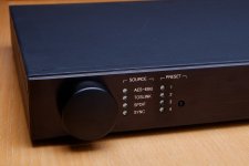
FS: MiniDSP 4x10HD with original box and accessories - Tom's Bargain Basement

*** SOLD ***

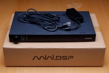
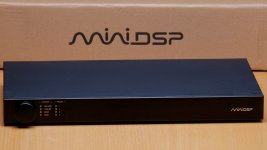
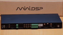
I have upgraded to the MiniDSP SHD, hence offer up for sale: MiniDSP 4x10HD with original box and accessories.

Included:
  • MiniDSP 4x10HD. You can see my measurements of it here: MiniDSP 4x10HD review and measurements
  • North American power cord (it's a standard IEC cord)
  • Power supply
  • Original TOSLINK optical cable
  • Original USB cable
  • Rack-mount ears (never used)
  • Original box (both inner box as shown and outer box for shipping)

$349 USD + shipping (see below for estimated rates). (SOLD)

The best way to reach me is by email. Take my username here and add @neurochrome.com. You can also PM me, but I check email more frequently than PM.

Sorry. I didn't take pictures of the USB cable, TOSLINK cable, or the rack ears. They're all in their new plastic bags as they came from MiniDSP. Nothing too exciting... 🙂

It's in near-mint condition. The only thing that distinguishes this from a new one from MiniDSP is a few finger marks or rub marks on the top by the volume knob as you can see in the pictures. All the female terminal plugs are present.

You'll need a $10 plug-in from MiniDSP to program it. I'm happy to provide a link to the correct one.

Please include your full shipping address and phone number when you contact me. This makes it possible for me to invoice you directly from my website (neurochrome.com). That way you can pay by credit card or paypal. Your choice, though I do prefer credit card as the fees are lower.
If you're in Canada, I'm happy to take payment via eTransfer. That'll save you 3-4% in exchange fees.

I have commercial accounts with the various shipping companies, hence, can offer good rates. I've included a couple of examples below. Please contact me for your exact rate.

Shipping examples (all amounts in USD):
Canada (H9Kxxx, QC): $17 via FedEx Ground
US (90210, CA): $35 via UPS 3-day
Europe (4600, Denmark): $59 via FedEx International Economy

Tom

Attachments

  • MiniDSP-1.jpg
    MiniDSP-1.jpg
    322.3 KB · Views: 321
  • MiniDSP-2.jpg
    MiniDSP-2.jpg
    369.8 KB · Views: 311
  • MiniDSP-5_NoSN.jpg
    MiniDSP-5_NoSN.jpg
    412.4 KB · Views: 307
  • MiniDSP-3.jpg
    MiniDSP-3.jpg
    265.3 KB · Views: 297
  • MiniDSP-4.jpg
    MiniDSP-4.jpg
    223.3 KB · Views: 306

Celestion Ditton 12" woofer question(s)

I have two pair of Celestion Ditton series 12” woofers. One pair has the small dust caps, the other the large. I also have one pair of the Celestion passive radiators. Measuring with DATS there are differences between the versions. (These numbers are an average of the pair’s figures)

Large Cap Small Cap
FS 23 hz 18 hz
Qts .335 .259
Qes .353 .270
Vas 223 lt 412 lt
Type 2619 1600

Does anyone have any insight as to which version would have been used in which Ditton – ie: 66, 44. 25? Also, were the passives from the 66 and the 25 the same? If not, how does one differentiate as I can find no identifying markings on them?

3.5mm 2 output Audio switch with SHIELDING?

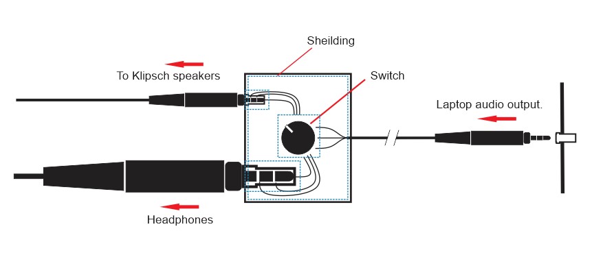
Hi, I'm interested in building a 1 input 2 output (3.5mm) A/B switch. At first I was looking to purchase one, but all the small units like I need have reports of noise being added to the signal because of poor, or no shielding. I've found several instructables on building something I can use, but none mention shielding. Any suggestions or ideas on how to achieve this? I created the image as I imagine it would work?


AudioSwitch.jpg

Meazzi echomatic help req

Nooby, at the very early stages of learning,
I've built this a couple of years ago and shelved it, but now I've got time on my hands it's back on the bench
I'm having trouble with hum and poor volume on the echo , I've got the oscillator running at 48k I don't know wether that's acceptable?
When I turn the echo pot up, it hums , I've put a 100 ohm resistor on the centre tap of the transformer for the heaters, but I don't really know if its the heaters or not.
I would be very grateful for any help, or suggestions, thankyou

Attachments

  • image1.JPG
    image1.JPG
    176.1 KB · Views: 206
  • IMG_4594.jpg
    IMG_4594.jpg
    659.8 KB · Views: 169

Weiliang DAC7

Bought in Diyhifishop a Weiliang DAC7 with several addons like OPA627, 1PPM 12M TCXO and an interface CM6631 USB module (driver-CM6631_6631A 1.01). Works well, sound clear, detailed and firm. But two problems occurs and hinders its use both windows7 as win8 (x64)& Foobar2000@WASAPI push mode:

- Often when I boot up the PC driver CMedia not locate the DAC via USB, then is 44.1 @ 16 bit, but it should be 192K @ 32bit. To resolve, I have to unplug the USB cable and then reconnect.

- Playing music, when change sampling frequency 44.1KHz for any other, makes a huge bang, and may even damage the speakers.

Forgive me for my bad english.
Can anyone help us please?

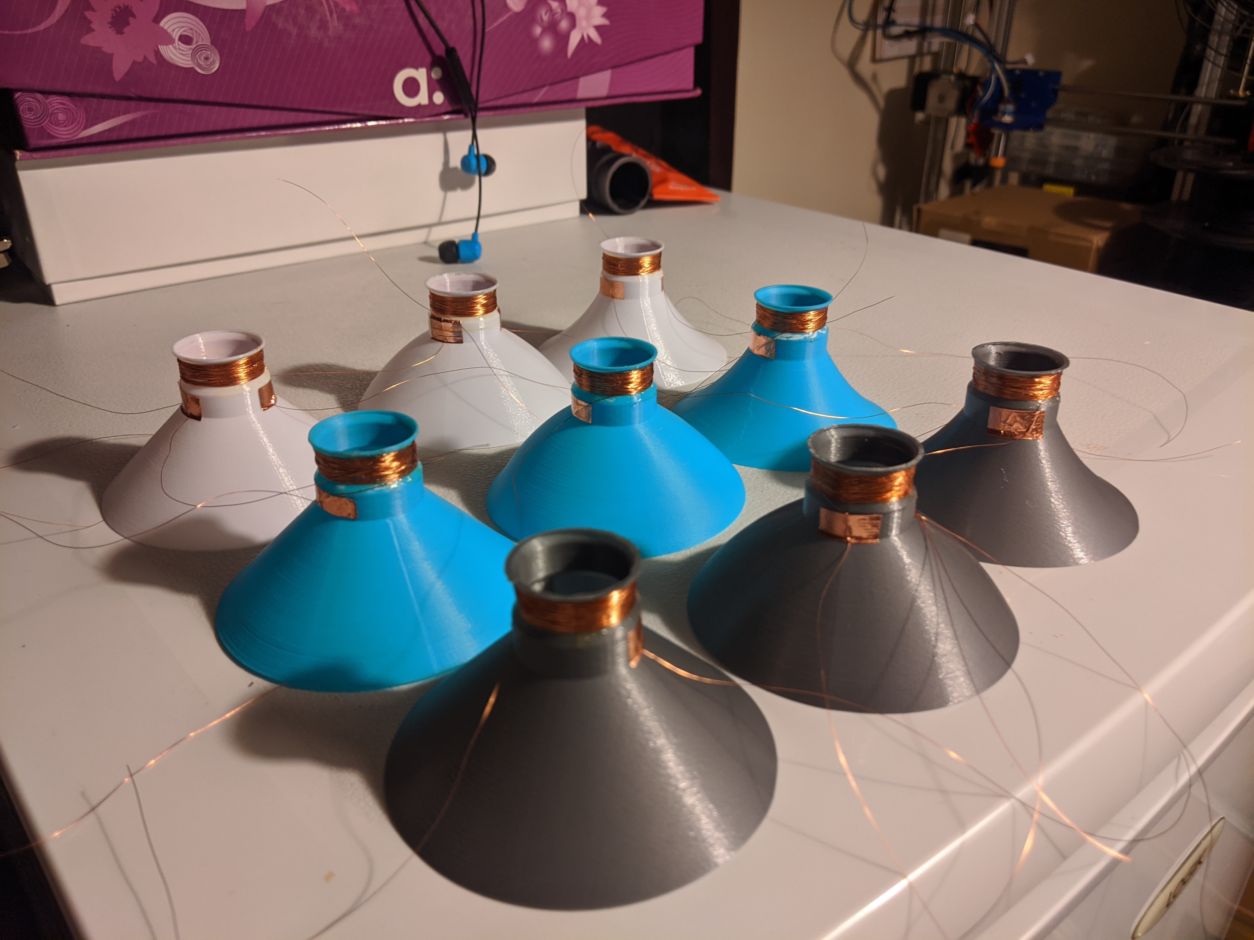
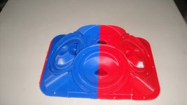
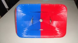
Cone Test Platform - 3D Printed Speaker Drivers & Experimentation

Hello everyone

I have posted before about my normal builds years ago, and my full range FD51 and FD61 drivers. FD51 is a low power series made for people to attempt and see that 3D printing has potential. FD61 came before and was more capable but more complex and failed as a kickstarter.

I have started a series where I will be testing different materials with 3 different cone profiles to look at how they react and how viable they would be as materials to use moving forward.

This first video was using common base materials, PLA, PETG and ABS. Just posted in case any of you are interested in this side of the hobby.

EWpHAiHWAAE1Ijs


YouTube

Paul
  • Like
Reactions: Naturlyd

3-Way Crossover - adding gain and summing stages

Good morning, good evening all !

I'm asking for your help.

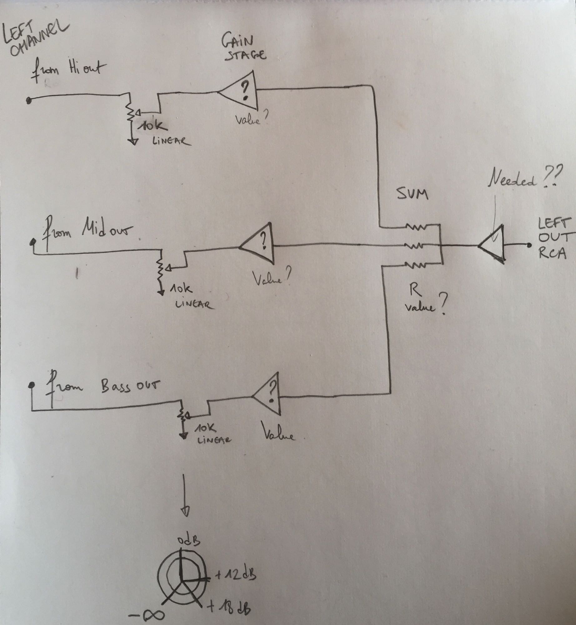
I would like to add/create a summing and a gain stages to an existing crossover design (from the 3-Way Linkwitz Riley Crossover circuitry by Rod Elliott) but my skills are not sufficient.

How could I correctly set the gain stage as follow ?
Potentiometer fully counter-clockwise = full kill
Potentiometer at 0 = unity gain
Potentiometer fully clockwise = +18db

How could I summ the Hi/Med/Low channels ?

My idea :
9gDyj.jpg


3-Way Linkwitz Riley Crossover circuitry by Rod Elliott :
https://i.goopics.net/wZNRZ.gif

Would you mind helping me out with the design and components value?

Thanks !

Hello from Dortmund, Germany

Hi, I'm Arien and I live in Dortmund, Germany. I've been interested in all things HiFi for as long as I can remember. I joined these forums when I was 17 years old, that's 17 years ago. I never contributed much at all because most of the discussion here went way over my head. I did oftentimes lurk and read whatever was of interest to me. Nowadays I can at least claim to have an idea of how much I don't know - so here I am 🙂

I was trained as a linux systems administrator specializing in Voice over IP but that was a long time ago. I still install linux on anything I can get my hands on but I'm not an "IT professional" anymore, for what it's worth.

My interests are PC audio with a focus on Free/Libre software and Linux, DSP processing and room correction, active speakers with MFB-/Servo woofer systems. While I don't mind spending money on my hobby, I do try to keep it budget-conscious.

Also I like to tinker with vinyl records - just for the fun of it. I'm not the person who is going to tell you it 'sounds better/warmer/whatever'. For me vinyl playback is a nice mix between a brain teaser and an exercise in mindfulness. The brain teaser part of it is about making the most from clearly sub-optimal prerequisites (without going broke). The mindfulness aspect is about physically putting on a record, looking at the cover, reading through the liner notes. A nice break from having millions of albums available at your fingertips.

Anyway, thanks for not deleting my account after I only made one post and then went silent all those years ago. I have many questions and I'll try to be helpful with those few answers I can provide.

Another Gday from Oz

I'm Keith and I've dived down the rabbit hole that is the Pi media streamer. I've ended up here to learn a bit more about it, and in particular, linear power supplies and the stuff that takes the Pi streamer from something thats cobbled together to something thats properly thought through, looks great and works well.

I have a technology background spanning close to four decades now and an enthusiast audio background that has included homebrew amps and speakers at one end and exotica at the other.

These days rocking a small room system of PSB speakers and sub, Yamaha power and streaming with digital files stored on a NAS. It sounds great and the plan is to replace the Yamaha streamer with the aforementioned Pi streamer and Moode or something like it to make the music more accessible.

NAD 116 schematics

Hi!

Does anybody have schematics of a NAD 116 Preamp? I have some slight problems with mine (sometimes powering it on results in several clicks of a relay and flashing power-led until it stays powered after a few seconds) which I would like to try to repair.

Further... does anybody have an idea whether this remote link it has could be used to remote-power on/off my (almoust finished) aleph5?


Thanks,
stegmaie

Non-Wet bipolar litycs speaker caps ?

Hi,

I tried to find more about bipolar lytic caps lifespan and loudspeakers because if finding some with capacitance that raise despite fall after 30 years ! Which are modern caps technology as made in the 80s or 90s.

Had already good answers about that and of course the question is not about changing it r not but more about understanding

I found ater some googling than a lytic cap should be sized around 50% to 75% more voltage than the circuit allows for the best lifespan because :

after long time caps spec with undersized voltage rating loose their efficienty, mainly ESR then see the capacitance decreasing. Ok it is known.

But I also read than oversized voltage ratting of caps above the 50 to 75% oversizing rule may introduce with time an increase of the capacitance !😱

I saw no reference about ripple limits & caps life span in this testimonial though... But if speaking about voltage and speaker filters : how one can size the voltage of their bipolar caps ??? Same voltage seen when a cap is in serie in front of a driver and when it is in // with it before it sees the voice coil - plus and minus shunt position in the bass and band pass bass section, impedance correction network- ...


Now about the raw and smooth etching and ESR on lytics bipolar caps as their dielectric material. Is anyone aware of solid type dielectric with some brands about their lytic bipolar caps ? Are they use also water to reduce the ESR of their dielectric gel in their best ESRed caps (smooth foil are said to be 0.025 ESR only but is it due just because the smooth foil vs he rough foil they use for high capacitance caps ?

Rephrasing it: because best ESR bipolar caps would have weter dielectric cause watered means faster drying and gasing so reduced lifespan (of the ESR and capacitance stability) ?

Aware of solid dielectric bipolar lytic caps on the market ?

For the story of it I bought some bipolar caps from Mundorf and JB in a famous online speakers german shop... the capacitance tolerance of the Mundorf raw foil Ecap (10 uF) was up to 12% to 17% instead the 5% advertised. JB was nearerof its 5% with 6% to 9% uper capacitance on a high 100 % value and 1% on a 470 uf cap

sorry, a little metaphysic question, in real life one would go active filter or spend for film caps in their filter what ever the capacitance (if the wallet is ok).


Uh, I'm going to test a speaker filter with circuit polarized caps I measure myself because on hands by putting two in serie in a + - - + arrengment hopping the ripple curent limit is ok for a speaker (yes I know such caps have a much higher ESR... but that's for tests purpose)

Beyond the petite Onken

Hi everyone,

About two years ago, we started to discuss here what would become a great project for me, the building of Eijiro Koïzumi's petite Onken design around a pair of Great Plains Audio 414-8B:

http://www.diyaudio.com/forums/multi-way/253853-la-petite-onken.html

Since then, I had the chance to try it two ways with TAD TD-2001/Arai A-480FL with very good results. Last fall, I moved forward with Onken OS-500MT driver and Onken OS-5000T tweeters. So it is now a 3 ways design. This put the system to a new level of enjoyment.

In the last months, a thread captured my interest on a french forum. It was about Onken's WB300 speakers. This one is like a mini-VOTT with a smaller footprint and uses a 414 from Altec. Since my desire to get something more efficient, the perspective to add 3-4 dB with the Onken WB300 attracted me. But, gain to loss, the bass respond would not be the one of the petite Onken. It quickly appears that a design with the 416-8B would give more efficiency and more bass.

I started to talked about this around and some members suggested few things: Onken 360l, VOTT, Altec 19, etc... I even saw an interesting speakers in Ahikiko Kaneda's second system (first picture) close to what I'm looking for.

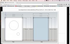
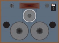
The fact is that I don't have a lot of space and WAF for something more larger and higher. Here's where André's (AJMARS) idea pops up with the suggestion to keep the same face dimension of the petite Onken but with a deeper enclosure. Bingo! He calculated me a 220l enclosure this way. This gives a 8.8 cubic feet, tuned at 29 Hz (second picture).

All in all, the specifications of this project are around these elements:

-use of GPA 416-8B;
-similar face dimension as the petite Onken;
-improve bass response;
-improve sensitivity;
-use of Baltic Birch plywood, 25mm;
-to use with Kanéda 228+ (29W/8 Ohms) amplifier or PSE 300B (15W/8 Ohms).

This thread is created to discuss this project.

Sébastien

Attachments

  • Installation Kaneda 2.jpg
    Installation Kaneda 2.jpg
    580.1 KB · Views: 1,961
  • Plan 1 André projet 416.jpg
    Plan 1 André projet 416.jpg
    377.3 KB · Views: 2,221

Why would someone wire a tweeter to bypass the crossover

I bought some JBL Arena 120,s, they are neat wall mountable speakers, supposedly capable of decent volume and power handling, perfect either side of the TV. They generally sound good but the occasional odd sound comes through, it seems more frequent with female voices and Latin pop of all things, a kind of gravelly harshness.

Curiously, I opened them up and the previous owner had wired the tweeter direct to the speaker post and left the woofer to the crossover. It was obvious because the new wires were just wound on, not soldered or with spades. I contacted previous owner and he just said he sold them for a friend, knew nothing about the wiring.

I removed these wires, connected the proper tweeter spades which were left wrapped up, it sounded better, I think, but I have always had my doubts they were right, the female Google Voice for example and sci-fi slidy doors (think Star trek) sound awful. I plug in head phones and it sounds OK.

Why would someone do this, are tweeters likely to be ruined permanently after bypassing the crossover. Are there any tests other than listening to see if tweeters are duff. I like the speakers and would be hard to replace them, so I am considering sourcing replacement tweeters.

FREE access to AudioXpress and Circuit Cellar

The publishers of AudioXpress and Circuit Cellar are offering free access to the May, June and July editions as a concession to the audio amateur stuck inside at this time. Just sign up to gain instant access to the May editions immediately.

Audioxpress Opens Up During Lockdown - Free Access to Digital Editions

The May edition of AudioXpress has an article about Mike Rothacher's delightfully named MoFo amplifier, as featured on this forum.

Help! UMIK-1 - Minidsp - Openbaffle -

Hello to all!

I have been doing a long term project and for 5 or 6 years the idea led to me where i am now...the crossover phase.

I have a good soundcard, the mini dsp 2x4, the Umik1 and my 4 amps.

I have a open baffle speaker (2 way). One full range and 2 woofers in each speaker.

I've been reading some documentation about the Rew software and MiniDsp.

Can someone tell me exactly what steps do i have to do now? i have some doubts. So, to start, i think i have regulate my driver volumes so they match. I measured the full range driver and adjusted the volume to 75db, also did this on the woofer to the exact same volume.

Done this with the Rew software, in generator. A pink noise in a "speaker cal" option. The mic was on the listening position pointing to the speaker it was measuring.

If this is correct, what now? i did a measurement but my results seam a little strange.

Thank you

Cerwin Vega Stealth 500.4

Hi everyone

I have a long time ago a stealth class d 4 channel amp. I bought all fault components and replace it. 4 irs2092, 8 irf540z and 4 irf3205.
The amp sounds great but one channel witout output. I cant found the real problem in the preamp area, i put the green wire for test. All 4 channel works great but the 10 ohm resistor inside the white circule gets veryyy hot, it smells a lot. So i test only for about 5 minutes and wait for cool down.

I cant find the diagram, the only thing i know about that resistor, is part of the 12 volt regulator. It conect one side to speakers ground, the other to a rs1m diode then to the input of the lm7812.

Anyone with a diagram or a idea of this??

Thanks

Am I beating a dead horse??

Repaired power amp board on my Marantz 1200 now has a ground loop problem- 60 Hz hum, noise drifts between channels. When I remove the right power amp board/heatsink from the chassis, the hum is gone. Sound hum doesn't increase/decrease with volume, I can move the signal wire to RCA input and the hum will go away, for awhile.

I'm going to remove the board from the heatsink and compare to the other channel, look for solder bridges, etc.

With all the time I've got now that I'm "working" from home, I'm thinking of building a Leach Amp or a Pass DIY amp to replace the Marantz.

Am I beating a dead horse?

MTX 1501d (old design amp)

Well I couldn't help myself and picked up another toasted MTX 1501d. Replaced all the power supply FETs and 2 gate resistors and the power supply fires up without issue.

Oddly enough, there is no switching on any of the output fets. LED 238 is not illuminated. Going off of memory here, but one opto-coupler has zero significant voltage on any pins, and it there is negative rail voltage on pins 5 and 8 of the optocoupler nearest the edge of the board.


Thoughts on were I should start?

FS: FiiO D3 (D03K) DAC Brand New in Box - Tom's Bargain Basement

*** SOLD ***

Brand spankin' new FiiO D3 (D03K) digital to analog converter. New in box.

I bought this for an experiment that I never started (beyond buying the DAC, that is). So the DAC is new in box. Or "NOS" if that sounds fancier... 🙂

Specs (according to the manufacturer):
  • Power supply: 5 V DC
  • Output amplitude: 1.5 V (0 dBFS)
  • Frequency response: 20 Hz - 20 kHz
  • SNR: ≥95 dB
  • Crosstalk: ≥85 dB
  • THD: < 0.008%
  • Size: 61.6 x 49.1 x 21 mm
  • Weight: 50g

You can read more on FiiO's website: D03K-FiiO---BORN FOR MUSIC

Included:
  • FiiO DAC
  • USB cable (for power)
  • Power supply (US plug)
  • Original box

$15 USD + shipping (see example rates below) (SOLD)

Please contact me directly if you're interested in buying. The best way to reach me is by email. You're welcome to PM me as well, but I check email more frequently than PM. Just take my user ID here and add @neurochrome.com.

When you contact me, please include your shipping address and phone number. This allows me to invoice you through my website (Neurochrome.com), which allows you to pay by credit card or paypal. Your choice, though I prefer credit card as the fees are lower.
If you're in Canada, I'm happy to take payment by eTransfer. That'll save you 3-4% in exchange fees.

I have commercial accounts with the various shippers, thus, get a pretty decent discount. I'll happily pass those discounts on to you, hence, my low rates on UPS and FedEx.
Below are examples of shipping rates for this sound card. All rates are in USD.

Canada (H9K..., QC): $11 by FedEx
US (90210, CA): $8 by Canada Post
Europe (4600, Denmark): $9 by Canada Post

This concludes my Bargain Basement for now ... unless you need a set of tire pressure sensors for an Audi/VW/Porsche. I have a set of those too... 🙂 They'll go on eBay.

Tom

Attachments

  • FiiO_DAC.jpg
    FiiO_DAC.jpg
    323.2 KB · Views: 168

Technics Stereo Integrated Amplifier SU-5

at first my Technics SU-5 Stereo Amp's Phono stopped working which refrained by turntable to give its output now recently its "left" speaker started emitting whistling sound, I switched the speaker from right to left and left to right. again after playing radio/tape for couple of minutes same whistling sound started from the speaker connected with the left channel. I disconnected the left channel speaker the sound now comes from the right channel speaker perfectly satisfactorily.

please suggest how to address to overcome both the above issues so that the amp is back to normal

50c5 push-pull for guitar?

Hey guys,
I'm new to the forum, but I've learned alot from reading your prior posts.

I'm no stranger to DIY. I've done many guitar pedals from scratch and know schematics and circuits well enough.

I have a moderate amount of tube experience. I know what not to do and I'm pretty familiar with the given sections of an amp.

I've never built a tube amplifier from scratch. That's what I'm hoping to do, however, my design skills are not near what I hope they will be in the near future.

I'm looking to make a guitar amp based roughly on the AA5 design.

I'm hoping to use a push-pull pair of 50c5's, with a 35w4 rectifier, and either a single 12a*7 gain stage or a duel 12**6 gain stage for a relatively low-noise, 2-5 watt output amp.

Now, I DO CERTAINLY KNOW the rules of these things. I WILL BE USING AN ISOLATION TRANSFORMER (I have no desire to die), I know to keep the chassis and ground seperate, etc... So, let's please not have that discussion over and over.

The main thing is, I haven't been able to find an output schematic of a 50c5 push-pull pair. I've found plenty SE designs but I'm looking for a little more output.
In addition, I'm not exactly sure what cheap output tranny would work (to keep cost down) and I'm totally lost on the splitter stage. I'm looking for 2-5 watts output at 8 ohms.
I'm also looking to use parts that I already have (with probable exception of the OT and possible splitter tube.)

Any suggestions?

Thanks.

Tube phono stage grounding

I am in the beginning stages of building a Hagerman Cornet Octal phono stage. I attached the schematic except I will be using a CCS on the cathode of the output. Also the PSU is in a separate box, already built, with H+, B+ and ground in an umbilical and a separate wire from chassis to chassis (the IEC ground is bolted to the PSU chassis, wire from there will go to the phono stage case).

I have a question about the grounding scheme. I have ran a separate wires from each component to a buss bar or star with good results in previous builds. For this build I was thinking of grounding sections together then each section to a buss or star.

I am using 5 lug terminal strips and thought about using one lug to go to the buss/star and have the components for each section go to their lug. For example on 1st lug, input ground?, R14, R15, C7- 2nd R16, R17, C8 - 3rd R18 (coming off CCS), R19, output?- the filter caps and resistors going to the anodes would be 4th, heater filter caps 5th.

Is this a reasonable solution? It does cut the number of wires quite a bit

If I do this should the L and R channels be on separate lugs, which would be 9 wires/lugs to ground total?

I tried to attach the pdf schematic.

Thanks

file:///C:/Users/david/Downloads/cornetoctal.pdf

Attachments

Avoid LittleDiode ! (UK)

Hi there,

I'm overhauling a french amplifier "l'Audiophile 50 W + 50 W" as describe in the French review l'Audiophile n° 1 new serie.

Amplificateur 50W+50W classe A (G.Chrtien)

This quite big amplifier (65 Lbs) was a kind of "French" Kaneda pure class A amplifier made by the Audiophile team (P. Johannet, W Walter, . . .). I got one 25 years ago and it's one of the best amp I've ever heard, far away above my previous Hiraga class A (20 W), kicking the bottom of lot of Mc Intosh - I know it's not a deal 😀. . . , or a Threshold SA3 . . . sorry Nelson !

The amp I get has burn his left chanel power transistors including the darlingnots/drivers ones, so I start to inquire genuine transistors to fix and overhaul the amp.

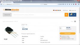
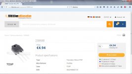
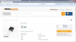
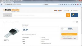
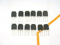
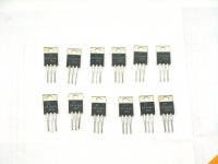
I've found (sell as) genuine power transistor Toshiba 2SD718/2SB688 and genuine drivers Toshiba 2SC2238/2SA968 in a provider based in UK named LittleDiode.

LD 2SD718 Toshiba.jpg

LD 2SB688 Toshiba.jpg

LD 2SC2238Y Toshiba.jpg

LD 2SA968Y Toshiba.jpg

I paid 211 € for 36 genuine NOS Toshiba transistor and here are the pictures of what I received :

2SD718.JPG

2SB688.JPG

2DC2238Y-2SA968Y.JPG

Only chinese copies ! ! ! This are not realy fakes but true fakes ! With my PEAK Atlas DCA75 transistor tester I'made a quick measurement of the Hfe of the 2SD718 and here you are : 60, 40, 42, 44, 35, 55, 53, 65, 39, 51, 60, 38. These transistors, with their -O suffix should have their Hfe between 80 and 160.

View attachment Transistor 2SD718 MOSPEC.pdf

Since I paid with PayPal I've asked to send back my delivery and LittleDiode had no choice but accept the return, I made this post to warn you against them. They clearly say on their website you will get genuine Toshiba semiconductors, and what you get is those ******** chinese copies out of specs - fakes indeed.

Since those refs doesn't exist anymore as NOS, I'll order True Toshiba pwr trans (2SC5200N/2SA1943N) and ON-Motorola drivers (MJE1530-31) withe serious dealers as Mouser or Digikey.

Next time don't waste your time and energy and avoid exotic provider as LittleDiode. they are swindlers !

Regards,

Jérome

Removable panel for speaker cabinet

Hi guys,

I am looking for some tips and pointers on how to have a removable panel on speaker cabinet to adjust the padding and such.

My woodworking skills are at very beginner level and have access to limited tools, however if I can work out how to have one of the panel on the speaker cabinet that can be removed and affixed again, that would be great.

Recently, I built these speakers and I simply used glue and screws to fix the panels and now I am stuck with them as I cannot alter speaker wiring or acoustic padding.

Can someone please point me to right place for removable panels (youtube video would be nice).

Need help with an 805 based tube amp

Hoping someone can help here...

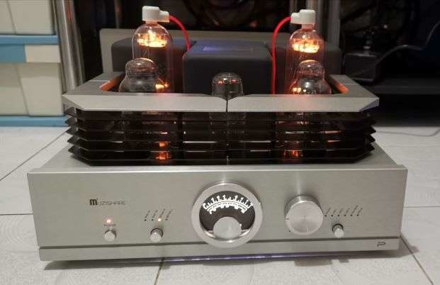
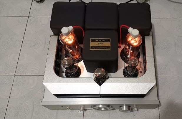
I just purchased a Muzishare R100 Integrated Amp. This version of the amp runs 805 tubes, with a plate (anode?) cap on the top. There is a non-detachable red wire with a ceramic cap on the amp, that connects to the top of each 805 tube.

I got it at a good deal, and it was supposed to be brand new. But, when I plugged it in, I found one of the 805 tubes wasnt working, and no sound coming from that side. I swapped the 805 with the other channel, to confirm that one of the 805 tubes is bad.

Im looking to replace the 805 tubes with something better, but found very few new 805 tubes with the top anode plate cap. There are the PSVANEs that are about $120 a pair, and COSSOR (made by PSVANES) that are $250 a pair.

There are many more options of 805 tubes without the top plate cap. Plus, I think the tubes without the top cap and wire look much cleaner on the amp. I was wondering, can I use 805 tubes without the top cap? And just leave the cap wire disconnected, or have it removed from the amp entirely?

Before you ask, I received no manual with the amp, and cant find any online. Specs are posted at bottom of this thread

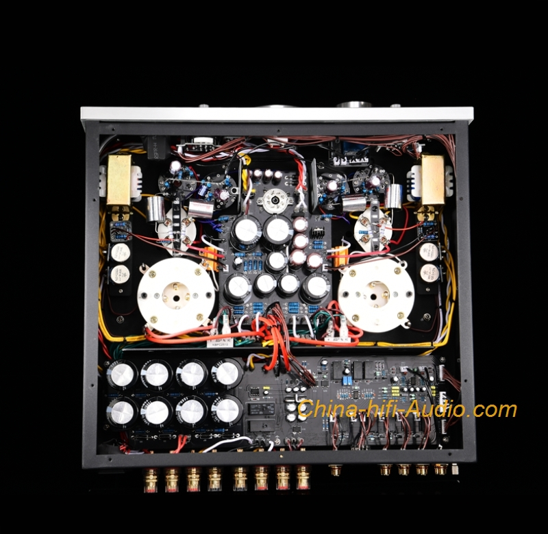
pics of the amp
p4pb18613617.jpg

p4pb18613618.jpg

Muzishare-R100-300B-845-Single-ended-Class-A-Integrated-Amplifier-power-Amp-Phono-3.png


Features:

1. Handmade, the main circuit is scaffolded.
2. Two EI-type single-ended output transformers with high-grade special technology and high-quality broadband response and high quality made by Z11 core.
3. High-voltage power supply and filament power supply independently use two high-power power transformers with Z11 iron core and special materials.
4. The front stage uses two 12AX7 and 6SN7 vacuum tubes; the push part uses two 300B tubes to directly splicing to the latter stage. The tone is full and delicate, the analysis is good, the dynamic is abundant, and the atmosphere is open.
5. The latter stage uses two 805 vacuum tubes for Class A single-ended power amplification.
6, six groups of signal input (PHONO, LINE1, LINE2, LINE3, BAL ANCE, PRE IN); this machine has added a balanced input function and pure post-level function.
7, boot high voltage delay and mute delay function (about 30 seconds).
8, select Japan AL PS high-end potentiometer.
9. Easy-to-install plug-in vacuum tube protection cover.
10. Peripheral power tube bias current adjustment function and power output level meter sensitivity selection file.
11, soft, pure and smooth, suitable for all kinds of music

Technical Parameters:
Rated output power: 50W+ 50W(RMS)
Harmonic distortion: 1% (1kHz)
The whole machine frequency response: 15Hz~35kHz (-1.5dB)
Input sensitivity: 240mV; pure power amp: 1000mV
Input impedance: 100 kohms
Output impedance: 4 kohms, 8 kohms, 16 kohms
Signal to noise ratio: 92dB
Output balance: <1dB
MM input impedance: 51 kohms
MM voltage gain (1KHz): 40dB
MM RIAA bandwidth: 0.25dB (20Hz to 20KHz)
Net weight: 42kg
Gross weight: 48kg
Power consumption: 450W
Use vacuum tube: 12AX7x2, 6SN7x2, 5U4G x 1, 300Bx2, 805x2
Volume (WxDxH): (430x435x265) mm
Power supply voltage: AC 230V (+- 5%) / AC 115V (+- 5%) (50Hz/60Hz)
Working Temperature: 0°C to 40°C, Humidity: 20%~80%
Storage temperature: -20 °C to 70 °C, humidity: 20% to 90%

Is upgrading worth it?

I'm trying to decide whether it's worth the pain to upgrade the stereo in my car or not. I have an 05 Mini Cooper with the harman/kardon upgrade, and even though it's the higher end stereo, it's still disappointing to me at least. I would hate to imagine how bad the standard stereo is. Maybe I'm expecting too much out of a car stereo, idk, atleast compared to the stereos in my friend's cars it sounds better, but it still doesn't match anything I have at home, and I don't have anything high end, just a few boomboxes I built and a pair of pretty decent computer speakers. The hk in my car sounds worse. If I were to sell the parts currently in my car, I've figured I could get maybe $500 out of the amp and the speakers. If I were to spend $800 or so in the aftermarket and install everything myself, do you guys think I would get a good jump in some quality? Another problem is, although I love the car, there's a lot of road noise, which is making me doubt I'll get anything out of upgrading, but who knows, maybe I'm wrong, I hope I am. I don't care about a fancy headunit or anything, I'm perfectly happy with just an aux input, I just want a decent jump in sound quality, something on par with the worst sounding system in my house atleast. Do you guys think it'll be worth it?

FS: Two complete HiFi2000 3U Disspante Chassis's

I have two new, unused HiFi 2000 3U Dissapante chassis's with 10mm Black faceplates for sale. The chassis include left and right heat sinks that can dissipate about 75W per side, so this would be good for any stereo A/B class amp, and for a smaller Class A amp like the FW F5, F6 etc. configured as a mono bloc. I am asking $125 ea with free shipping by USPS. You can buy both of them for $225.00, again with free shipping.

These are really nice chassis's that come as flat panel kits, making drilling holes, etc. easy. Much better than the Chinese-sourced chassis's on eBay that I have used in the past.

Fried My PCB

I just hooked up my first from scratch PSU. The fast fuse immediately blew and I thought maybe inrush current was the culprit. However, when I tried a slow blow fuse, the same thing happened and you can see the burn on the bottom of the board. I don't see anything obviously wrong with my board layout, but then again I have been looking at it for hours on end so I think I am just getting tunnel vision. Help?


20200416_184842.jpg


20200416_184842.jpg

Attachments

  • 20200416_184835.jpg
    20200416_184835.jpg
    974.1 KB · Views: 320
  • LM317 PSU-2b.asc
    LM317 PSU-2b.asc
    4.5 KB · Views: 80

Best full range speaker WITH equalisation

Hi,

I think everyone has a favourite full range somewhere. However I am looking at full rangers where if it used by itself is not impressive,maybe a lot of peaks and valleys but if you decide to equalise them via DSP or tone controls, becomes a new thing altogether.

For example you may find a speaker very shouty, but after equalisation the speaker might be very detailed without the shoutiness.

As for myself, I have been messing around with a Faitalpro 3Fe22. However the frequency response tend to be on the rising end with increasing with frequency. This makes the speaker sound a bit thin. However once equalized via DSP, they prove to be extremely detailed and very pleasant to listen to.

Any thoughts?

Oon

Fixing a dented flat dust cap

Forgive asking this because I know there are multiple threads out there, but is there a 100% foolproof method to fix a dustcap that doesn't risk permanent damage and gets it back to normal?
My thought is to use a bent pin -- insert it and then crowbar it back out. Thoughts?

Also, if I leave it like that, does it have any affect on frequency response whatsoever? I can't get a definitive answer on this

Attachments

  • IMG_2302.jpg
    IMG_2302.jpg
    1,016.4 KB · Views: 137

Measuring a Pair of Retro Tesla ARO 666

So I live in one of the last houses that will be torn down in a massive to-be development project... which leaves some amazing alleyway finds. I found a giant old Sears-Simpsons phonograph cabinet... thing. Wasn't expecting much, the amp turned on but static all over and the turntable was completely busted. I hooked up the speakers to a different amp, though, and was surprised by the low end. They weren't amazing, but given the setup was 3x tweeters and a single woofer (with a pair of caps as a crossover) with no enclosure I was surprised. The tweeters were trash and the comb was obvious, but the woofers seemed decent. They're Tesla ARO 666's (found a doc here, see page 4).


They're rated at 5W max though, but I thought I'd measure them to see if they'd do well in a low-power nearfield 3-way. I'm very new to audio, so I suspect I measured something wrong. My process was (after disconnecting the tweeters, of course):

  • Play a log scaled sine sweep at a decent volume. I'm not trying to get precise SPL, just the approximate response. I don't have a proper measurement mic, more of an all purpose field one.
  • Take the F.T. of the recording
  • Multiply with the F.T. of the inverse sweep (convolving since this is in frequency domain)
  • Use the complex amplitude as the frequency response and the complex phase as the phase
What I got seems too good to be true:
kLTD9nC.png


Any advice on what I might be doing wrong, or could I have actually stumbled into a retro gem? If they are that good, how do you go about cleaning and repairing a driver from the 70's? What would be a good use for something with that low of power?

Dave Slagle ( Intact Audio ) IT and OPT

Hello all,
Walking away from the DIY part of my audio disease. I've got a lot of high quality tube stuff that will be coming up.

First, a pr of IT and OPT from Dave at Intact Audio.
Originally wound for the EML 20B and EML 2A3 or 45.
The OPT are specced at. 5K/12 ohm ( I'm a single driver enthusiast ) and are wound on a 49 % nickel core. The IT, while wound for the 20b, can be re-gapped as necessary for other tubes ( Dave was going to regap for the 26 triode I was planning on using to drive an EL84 ). The core is nickel.
I took delivery from Dave in the Sumer of 2016. Been in the box ever since.'

Both are brand new. Never even mounted on anything.

Haven't got a clue how to post pics here. Send me an e-mail if interested and I'll attach them to the return.

These are as good as it gets. They don't call him the Slaglemeister for nothing.
Take a look at the Stereophile article by Herb Reichart ( March 2020 ).

Now for the sticky part.
The OPT were $ 1200/pr. I'll let them go for $ 800.00/pr. Shipping and insurance to the lower 48 on me.

The IT were $ 500.00/pr. I'll let them go for $ 325.00 pr, same shipping conditions.

I will ship internationally. However, be aware of the following.

I will not lie on a customs form.
I will not ship the cheap way ( first class mail international ). It will have to be priority or express so it can be insured. these are heavy, and it will be expensive.

International shipping and insurance costs are on the buyer.

Thanks for looking

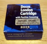
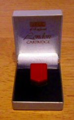
For Sale - Decca London Gray Phono Cartridge - Export Model

!!! SOLD !!!


This is the highly desirable "Gray" version of this legendary cartridge. Hand selected at the Decca factory in England for even better specifications than the already spectacular Decca London "Blue" cartridges, Gray "Export Models" were only available outside the British Isles. Frequency response for a Gray is substantially flatter than an "ordinary" Decca. Gray and Blue cartridges feature a spherical stylus.

I'm asking US$549.00
, shipped to the continental United States, but I will entertain reasonable offers.

Included:
  • Decca Gray FFSS phono cartridge - Export Model - with factory protective cover
  • Original mounting adapter for standard head shells (removable for use with Decca tonearm)
  • Original inner "jewelry" box
  • Original outer box with "Export Model" label ("Not for sale in the British Isles")
  • Unopened mounting screw/connector packet (I'm not sure this packet is Decca original)
  • Original installation/specification booklet
  • Laboratory frequency response chart with certification from Paoli High Fidelity Consultants
  • Paoli High Fidelity Consultants brochure (I think they were a Decca importer)

Condition:[/SIZE][/FONT]
  • The cartridge, protective cover and mounting adapter are all in EXCELLENT cosmetic condition.
  • Since I no longer have a turntable that uses a standard tonearm, I cannot test the cartridge.
  • Since I no longer have a stylus microscope, I cannot attest to the condition of the stylus.
  • Original outer box is in FAIR to GOOD condition, showing marks and wear from storage.
  • Original inner jewelry box is in EXCELLENT condition.
  • All documents are in EXCELLENT condition - the frequency response chart is clearly legible.

Attachments

  • Box.jpg
    Box.jpg
    806.9 KB · Views: 403
  • In Jewelry Case.jpg
    In Jewelry Case.jpg
    339.1 KB · Views: 374
  • Bottom - Close up 2.jpg
    Bottom - Close up 2.jpg
    583.6 KB · Views: 374

PA Amplifier and Equalizer APO gain knob do not match?

Hi, my PA amplifier has the double watts RMS needed for my speakers, so I put the gain knob -3db. I started using Equalizer APO as a DSP for my sound system, and I want to have the knobs on the amplifier all the way up and put the -3db gain in the pc. But it's not the same, I tried to match the volume, and I ended up putting -6db to -10db in equalizer apo, someone can explain why?

How much -DB I put on Equalizer APO to match the -3db on the PA amplifier?

Thanks...

FS: Monolith Magnetics Transformers

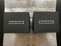
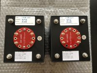
I have a pair of high quality Monolith Magnetics S9 3K3 double C core single ended output transformers and a pair of Monolith Magnetics Amorphous Core ITA-01 1:1 interstage transformers.

The transformers were bought from Monolith Magnetics in 2019. Both pairs of transformers are in 100% perfect and like new condition.

The transformers were used for a few months in a pair of very nice 300B SE amplifiers, but I have since moved on to other projects and they have to go.

The S9 transformers are priced at 450 Euro for the pair. SOLD

The ITA-01 interstage transformers are priced at 400 Euro for the pair. SOLD

The transformers will be shipped from Denmark (EU). Please email me for a shipping quote.

Attachments

  • IMG-2164.jpg
    IMG-2164.jpg
    1 MB · Views: 522
  • IMG-2165.jpg
    IMG-2165.jpg
    1.1 MB · Views: 503
  • IMG-2334.jpg
    IMG-2334.jpg
    1,018.4 KB · Views: 495
  • IMG-2332.jpg
    IMG-2332.jpg
    906.6 KB · Views: 591

free 1 Metlako unity horn

Hello,
I have 1 free Metlako unity horn to the first person PM.
I would need a pre-paid shipping label mail to my address. I will box and let you know what is the box weight.

I will ship by the end of May.
https://www.diyaudio.com/forums/multi-way/342019-metlako-affordable-unity-waveguide.html
Stay Safe!

Attachments

  • DSC03270.JPG
    DSC03270.JPG
    126.1 KB · Views: 148
  • DSC03271.JPG
    DSC03271.JPG
    135.8 KB · Views: 145

Four ways system

Hi, I have readed this old post https://www.diyaudio.com/forums/multi-way/178999-enclosure-jbl-2226-subwoofer.html in particular SBP - Almighty Subwoofers by Stig Erik Tangen where there is a project for a subwoofer with a JBL 2226h.
I want to built a 4 way system with these components (the picture is an ipotetic front):
JBL 2226h x 2 woofer 15”
JBL 2123h mid bass 10”
JBL 2425h mid high 1” with wood horn
JBL 2405h tweeter
My idea is to use two woofer (I have) for box. Did someone realize the project of Stig Erik Tangen? What do it change using two woofer? Can someone help me?
Kind regards
Giuseppe

Attachments

  • JBL 4350 clone.jpg
    JBL 4350 clone.jpg
    422.8 KB · Views: 225

Parallel selectable Caps on Baxandall Filter

Hi, I'm trying to mod the berocca pre amp for bass by robs mod for a friend by adding an option to select between 2 set of capacitors in the baxandall filter to have two centre frequencies for the treble control (one a 4.5kHz and other at 11kHz). When I tried that circuit it sounded like a very muddy and bad fuzz, saturating every thing and cutting off sometimes. Also noted that if de-soldered on combination of caps from the pcb and the switch the switch didn't cut off but had the same sound only that at a very low volume level. Can this be implemented as it shows in the photo or I can't put a parallel cap in the baxandall even with a switch?


Imgur: The magic of the Internet


Thanks!

An externally hosted image should be here but it was not working when we last tested it.

About cbb22 105j400v capacitors

Hello

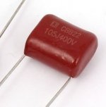
I have few cbb22 105j400v capacitor, some web site say that they are polypropylene film capacitors, others say that they are polyester film capacitors. I don't know who made them.

Anybody know if they are polypropylene or polyester film capacitors and who made them ?

I include a photo of my capacitors.

Thank

Bye

Gaetan

Attachments

  • Capture2.jpg
    Capture2.jpg
    38 KB · Views: 200

Interest in dual regulator LT1083 pcbs?

Hi folks,

I'm finishing a pcb-layout for a voltage regulated psu-board for dual rails (like +/-35V) which uses the LT1083/LT1084/LT1085 regulator (the high power (7 A) TO-3P variant) for both polarities. I'm going to power my power amp with it.

It is very small in size, currently 50x70mm, double sided, has very fat tracks (150mills for the regulated side), has well separated tracks (20mills average track clearance) and will be manufactured with heavy copper (70um).

One board gives both voltages (adjustable from +/-1.25V up).

This is the first time I'll order at this boardhouse, but I've heared the board edges are cut - not milled - so probably don't look that perfect as you're used to. However this does not have an impact on functionality (just looks).

Big advantage - they're cheap.

Cost depends on number of boards, rough guess is about 18 Euros per board for 4 pcs (that I need), of course dropping with every board that comes in addition.

I'm looking if there's interest, so we could order more boards and benefit from a lower price.

Have fun, Hannes

PS: I will post schematic and layout in the next few days.

Mounting driver inside out (Bandpass enclosure)

Let us consider the basic (4th order) bandpass enclosure. There are sealed and ported chambers. In most bandpass subwoofers, they are usually mounted driver in the sealed room, where cone facing ported room. What if we flip the mounting in the opposite direction? Says cone facing sealed room and magnet in ported room. Will the sound be the same? Does it need any modifications or just flip the driver without any mods?

A Yamaha Hyperbolic Conversion (HCA) Clone - The HHCA

Here I introduce the HHCA (Homage HCA) amplifier design. About a year ago I built an amplifier I "designed"... or more like copy-pasted and sprinkled some luck on 😀
It's a mix of the Yamaha MX-1 input stage, the discrete HCA amplifier from something earlier, and a more standard output stage (no Class G).

Wanted an 80's/90's Yamaha amplifier for a while but they are a bit pricey, so decided to roll my own.

PCB layout was designed with flexibility in mind.

I have tested this up to +/-31V as that is all my bench supply gives, but it has had a good thrashing on and off for the past year. It worked first time, even with a missing solder joint so not all of my output transistors were working, I didn't notice for a few months.... 🙄

If you power up all equipment at the same time, with a current limit on the supply to this design, with a large switch on thump present on the input, it will latch up until you power cycle. Either phase the power up of your equipment, or have a good few of these :drink: - remove the current limit, and pray to god it's ok.... Honestly I have had this happen twice by accident with my current limit set at 1A or so, but not with current set higher than this.

I have not made proper audio measurements, but I think it sounds pretty awesome, seems dead quite with my ear up to my tweeters, and doesn't do anything horrible if you mess around with the inputs when they are disconnected or feed it square waves.


HHCA 1.1 Schematic Small.jpg

HHCA 1 Picture Small.jpg

View attachment HHCA 1.1 Schematic.pdf

View attachment HHCA 1.1 PCB Front Layout.pdf

View attachment HCA 1.1 PCB Gerbers.zip

View attachment HCA 1.1 PCB Layers in PDF.zip

View attachment HHCA 1.1 Bill of Materials.zip


Warnings:
I have no interest if the Hyperbolic Conversion Amplifier (or hyper b******* amplifier if you prefer) actually works, but I think this sounds pretty good. Maybe if you remove the HCA part and hook the output stage to the input stage it might sound the same (maybe I should try that sometime).

This design should (theoretically) be good upto +/-75V if you replace the medium power transistors with KSA1381 and KSC3503 parts, and if any resistors start smoking just put bigger parts in 😉 - However these transistors have lower output capacitance and may impact stability!

Edit:

Knew I would forget something. Supply voltage with specified parts is +/-30V to +/- 50V. PCB is 2 layer, recommend 2oz copper if you want to push it a bit. Gain should be around 28dB. Input sensitivity...feed her till she pops! :devilr:

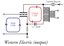
Western Electric Parafeed Output - cathode bypass?

I just completed a parafeed headphone amplifier. I had originally wired for the "Western Electric" output topology, shown below, without a cathode resistor bypass cap on my output tube (45). I was getting quite a bit of 60Hz noise on one channel, narrowed the source to some coupling to the right channel 45 filament regulator, but was unable to eliminate it.

DSCF5573.jpg

Western Electric Parafeed.png

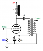
Instead, I added a capacitor across the cathode resistor, but kept the parafeed transformer return to the top of the cathode resistor, an output design discussed in one of John Broskie's parafeed Tube CAD articles.

TubeCad Parafeed.png

Here is my question - is the Western Electric topology and the design shown in Tube CAD one and the same, and the "bypass cap" across the cathode resistor remains out of the signal path? According to John, it does.

Regardless, it has created an AC path to ground for my 60Hz noise and solved my issue, I'm just curious why the Western Electric output does not use this capacitor.

Anthem Integrated 1 burned resistor

Hi all.. My amp burned out a screen grid resistor and two of 8 - EL84 power tubes or the power tubes burned out taking the resistor with them. In any event I can not find a replacement for the resistor a GS-3, 2.2K ohm 3 watt IRC brand rated at 1000 volts. It appears that the GS line if these resistors regardless of brand is obsolete and there appears to be none to be had @ 2.2k ohm. There is one resistor on the screen of each of the power tubes and each pair of resistors appears to be in series screen to screen to each pair of tubes.


Other series are available with similar specs but only to a maximum of 750 volts.


My intention is to find a suitable replacement and install 8 new resistors... question is with what?


Anyone else run into this problem? if so please share your solution... Much thanks, Bill
Projects by fanatics, for fanatics
Get answers and advice for everyone wanting to learn the art of audio.
Join the Community
507,703
Members
7,885,041
Messages

Filter

Forum Statistics

Threads
406,073
Messages
7,885,041
Members
507,703
Latest member
rtxftw